8. LOAD HANDLING SYSTEM
- 136 -
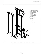
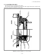
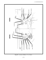
Fig. 8.3
Outer and Inner Channels (VM-77X)
8.1.2 CARRIAGE
The carriage has end rollers that roll along the inside of the inner channel, each installed on the end
roller shaft by bearings. The end roller shafts are welded to the carriage. The upper end rollers are shim-
adjusted while the lower end rollers are secured to the shafts with snap rings.
Longitudinal load is sustained by the end rollers. When the forks are raised to the maximum height,
the upper end rollers emerge from the mast top. Transverse load is sustained by the lower side-rollers.
1. OUTER CHANNEL
2. INNER CHANNEL
3. END ROLLER
4. SNAP RING
5. SLIPPER
6. NUT
7. PLUG
8. SLIPPER
9. SHIM
10. SIDE ROLLER
11. SHIM
12. SPACER
13. PIN
14. STOPPER
15. CAP
16. BUSHING
Summary of Contents for FB10-7
Page 2: ......
Page 4: ...No SEB 81BBE...
Page 8: ...No SEB 81BBE...
Page 9: ...No SEB 81BBE Fig 1 Overall Dimensions Unit mm in...
Page 10: ...No SEB 81BBE...
Page 28: ...1 BATTERY AND CHARGER 16 NOTE...
Page 30: ...2 MOTORS 18 DRIVE UNIT Fig 2 1 Drive Motor Installation DRIVE AXLE DRIVE MOTOR...
Page 42: ...3 CONTROL SYSTEM 30 Fig 3 2 Inverter Assembly 1 0 to 2 5 ton Trucks...
Page 43: ...31 3 CONTROL SYSTEM Fig 3 3 Inverter Assembly 3 0 to 3 5 ton Trucks...
Page 44: ...3 CONTROL SYSTEM 32 Fig 3 4 Controller Wiring 1 0 to 2 5 ton Trucks...
Page 45: ...33 3 CONTROL SYSTEM Fig 3 5 Controller Wiring 3 0 to 3 5 ton Trucks...
Page 133: ...7 HYDRAULIC SYSTEM 121 Fig 7 27 Remove the oil seal from the front cover...
Page 160: ...8 LOAD HANDLING SYSTEM 148 NOTE...

