8. LOAD HANDLING SYSTEM
- 142 -
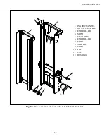
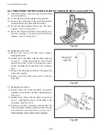
Fig. 8.9
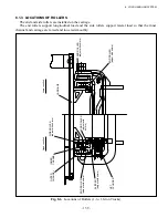
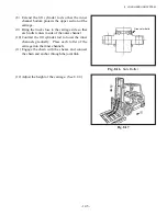
Fig. 8.10
8.2 MAINTENANCE
8.2.1 ADJUST LIFT CYLINDER ROD WITH SHIMS
After the lift cylinder, inner channel, and outer channel are replaced, the lift cylinder rod length needs
to be adjusted.
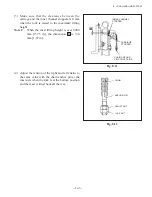
(1) Install a piston head on the rod of each left
cylinder without using shims.
(2) Extend the rod of each lift cylinder slowly and
examine the difference in the rod stopping time
when the rod reaches the stroke end between the
two lift cylinders.
(3) Add shims to the space between the rod and
piston head of the lift cylinder whose rod stops
first.
Shim thickness: 0.2 and 0.5
[0.0079 and 0.0197 in.]
(4) Adjust the lift chain tension.
8.2.2 ADJUSTING HEIGHT OF CARRIAGE
(1) Stop the truck on a level surface and put the
mast vertically.
(2) Keep the fork bottom on the ground and adjust
the projected amount
A
of the carriage lower
end roller to the value as shown in Table 8.1,
using the chain anchor pin at the mast side.
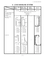
Table 8.1
Model
Mast Type
A
(mm [in.])
1 – 1.8 t
VM-81E
36 – 41 [1.42 – 1.61]
2 – 2.5 t
VM-81N
24 – 29 [0.94 – 1.14]
3.0 t
VM-39F
44 – 49 [1.73 – 1.93]
3.5 t
VM-77X
37 – 42 [1.46 – 1.65]
LIFT CYLINDER
FORK
TIRE
INNER CHANNEL
CARRIAGE END
ROLLER
PISTON HEAD
SHIM
Summary of Contents for FB10-7
Page 2: ......
Page 4: ...No SEB 81BBE...
Page 8: ...No SEB 81BBE...
Page 9: ...No SEB 81BBE Fig 1 Overall Dimensions Unit mm in...
Page 10: ...No SEB 81BBE...
Page 28: ...1 BATTERY AND CHARGER 16 NOTE...
Page 30: ...2 MOTORS 18 DRIVE UNIT Fig 2 1 Drive Motor Installation DRIVE AXLE DRIVE MOTOR...
Page 42: ...3 CONTROL SYSTEM 30 Fig 3 2 Inverter Assembly 1 0 to 2 5 ton Trucks...
Page 43: ...31 3 CONTROL SYSTEM Fig 3 3 Inverter Assembly 3 0 to 3 5 ton Trucks...
Page 44: ...3 CONTROL SYSTEM 32 Fig 3 4 Controller Wiring 1 0 to 2 5 ton Trucks...
Page 45: ...33 3 CONTROL SYSTEM Fig 3 5 Controller Wiring 3 0 to 3 5 ton Trucks...
Page 133: ...7 HYDRAULIC SYSTEM 121 Fig 7 27 Remove the oil seal from the front cover...
Page 160: ...8 LOAD HANDLING SYSTEM 148 NOTE...


