8. LOAD HANDLING SYSTEM
- 147 -
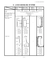
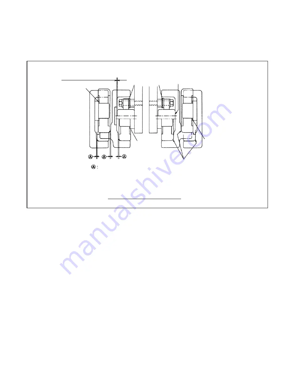
Fig. 8.20
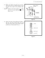
0 to 0.5 mm at upper side
SHIM
Make contact
with one side.
0 to 0.5 mm [0 to 0.197 in.]
Note: Apply grease to the end roller contacting surface of each channel.
SHIM
SHIM
SHIM
SHIM
Make contact
with one side.
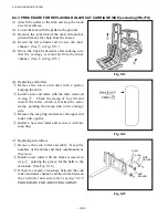
Procedure for Adding or Subtracting Shims
8.2.5 PROCEDURE FOR ADDING OR SUBTRACING SHIMS (excluding VM-77X)
Move the inner channel and carriage to one side of the outer channel. Measure the clearance between
the end roller at the opposite side and each channel.
Clearance between roller and channel: 0 to 0.5 mm [0 to 0.197 in.]
Summary of Contents for FB10-7
Page 2: ......
Page 4: ...No SEB 81BBE...
Page 8: ...No SEB 81BBE...
Page 9: ...No SEB 81BBE Fig 1 Overall Dimensions Unit mm in...
Page 10: ...No SEB 81BBE...
Page 28: ...1 BATTERY AND CHARGER 16 NOTE...
Page 30: ...2 MOTORS 18 DRIVE UNIT Fig 2 1 Drive Motor Installation DRIVE AXLE DRIVE MOTOR...
Page 42: ...3 CONTROL SYSTEM 30 Fig 3 2 Inverter Assembly 1 0 to 2 5 ton Trucks...
Page 43: ...31 3 CONTROL SYSTEM Fig 3 3 Inverter Assembly 3 0 to 3 5 ton Trucks...
Page 44: ...3 CONTROL SYSTEM 32 Fig 3 4 Controller Wiring 1 0 to 2 5 ton Trucks...
Page 45: ...33 3 CONTROL SYSTEM Fig 3 5 Controller Wiring 3 0 to 3 5 ton Trucks...
Page 133: ...7 HYDRAULIC SYSTEM 121 Fig 7 27 Remove the oil seal from the front cover...
Page 160: ...8 LOAD HANDLING SYSTEM 148 NOTE...

