1. BATTERY AND CHARGER
- 4 -
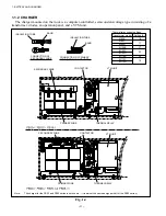
1.1.2 CHARGER
The charger mounted on the truck is a computer-controlled, semiconstant-voltage type consisting of a
transformer, diodes, an operation panel, and a VTM unit.
INSULATION TUBE
BAND
INSULATION TUBE
BAND
SECONDARY WIRE
CONTACTOR
VTM UNIT
PRIMARY WIRE
THERMAL RELAY
SECONDARY WIRE
CONTACTOR
VTM UNIT
PRIMARY WIRE
THERMAL RELAY
CONNECTION Of PRIMARY
WIRE (PORTION NOT USED)
CONNECTION Of
SECONDARY WIRE
Thermal relay current settings
Transformer model Setting (A)
M80B
18
M80C
11
M80D
M105B
37
M105C
20
M105D
M115B
29
M115C
15
M115D
Note:
The charger for the fB30 and fB35 series is not shown . (It is almost the same design as that for the fB20 series.)
Fig. 1.4
Summary of Contents for FB10-7
Page 2: ......
Page 4: ...No SEB 81BBE...
Page 8: ...No SEB 81BBE...
Page 9: ...No SEB 81BBE Fig 1 Overall Dimensions Unit mm in...
Page 10: ...No SEB 81BBE...
Page 28: ...1 BATTERY AND CHARGER 16 NOTE...
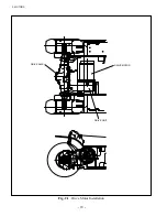
Page 30: ...2 MOTORS 18 DRIVE UNIT Fig 2 1 Drive Motor Installation DRIVE AXLE DRIVE MOTOR...
Page 42: ...3 CONTROL SYSTEM 30 Fig 3 2 Inverter Assembly 1 0 to 2 5 ton Trucks...
Page 43: ...31 3 CONTROL SYSTEM Fig 3 3 Inverter Assembly 3 0 to 3 5 ton Trucks...
Page 44: ...3 CONTROL SYSTEM 32 Fig 3 4 Controller Wiring 1 0 to 2 5 ton Trucks...
Page 45: ...33 3 CONTROL SYSTEM Fig 3 5 Controller Wiring 3 0 to 3 5 ton Trucks...
Page 133: ...7 HYDRAULIC SYSTEM 121 Fig 7 27 Remove the oil seal from the front cover...
Page 160: ...8 LOAD HANDLING SYSTEM 148 NOTE...


