1. BATTERY AND CHARGER
- 7 -
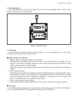
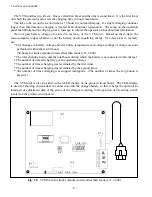
(3) Operation panel
The operation panel is located on the left side of the cabinet and equipped with a charger control
switches, lamps and service power outlet.
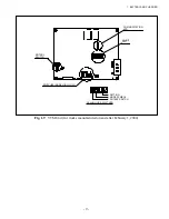
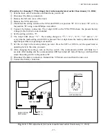
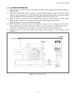
(4) VTM unit
The VTM unit is installed inside the right side frame. It sets the charging time for the battery
assembly by the signal from the operation panel.
■
Major features of VTM unit
①
Optimal charge according to battery’s state of charge
Conventionally, overcharge might occur when not so an exhausted battery is charged. On this
charger, the microprocessor judges the battery’s state of charge and changes the normal timer setting
within a specified range for optimal charge.
This setting voltage is compensated properly to provide optimal charge even if there are temperature
changes.
②
Super equalizing charge
The microprocessor counts the charging time and automatically provides equalizing charge when a
specified time is reached. The time setting for super equalizing charge is preset properly according
to the ambient temperature after temperature compensation. This function saves the trouble of the
operator’s bothering to press the equalizing charge button.
③
In case of power failure while charging
Unless power failure continues longer than 120 hours, battery charging is normally completed.
■
VTM unit
The VTM is mainly composed of its timer function. The microprocessor of the VTM unit determines
and sets an optimal duration of charging after checking the state of the battery.
Fig. 1.7
Operation Panel
Summary of Contents for FB10-7
Page 2: ......
Page 4: ...No SEB 81BBE...
Page 8: ...No SEB 81BBE...
Page 9: ...No SEB 81BBE Fig 1 Overall Dimensions Unit mm in...
Page 10: ...No SEB 81BBE...
Page 28: ...1 BATTERY AND CHARGER 16 NOTE...
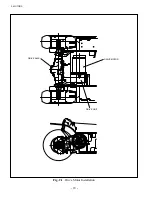
Page 30: ...2 MOTORS 18 DRIVE UNIT Fig 2 1 Drive Motor Installation DRIVE AXLE DRIVE MOTOR...
Page 42: ...3 CONTROL SYSTEM 30 Fig 3 2 Inverter Assembly 1 0 to 2 5 ton Trucks...
Page 43: ...31 3 CONTROL SYSTEM Fig 3 3 Inverter Assembly 3 0 to 3 5 ton Trucks...
Page 44: ...3 CONTROL SYSTEM 32 Fig 3 4 Controller Wiring 1 0 to 2 5 ton Trucks...
Page 45: ...33 3 CONTROL SYSTEM Fig 3 5 Controller Wiring 3 0 to 3 5 ton Trucks...
Page 133: ...7 HYDRAULIC SYSTEM 121 Fig 7 27 Remove the oil seal from the front cover...
Page 160: ...8 LOAD HANDLING SYSTEM 148 NOTE...


