1. BATTERY AND CHARGER
- 11 -
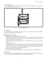
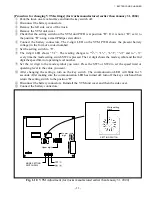
[Procedure for changing VTM settings] (for trucks manufactured earlier than January 31, 2004)
①
Park the truck on a level surface and turn the key switch off.
②
Disconnect the battery connectors.
③
Remove the left side cover of the truck.
④
Remove the VTM unit cover.
⑤
Check that the setting switch on the VTM unit PWB is at position “D”. If it is not at “D”, set it to
the position “D” using a small Philips screwdriver.
⑥
Connect the battery connectors. The 2-digit LED on the VTM PWB shows the present battery
voltage (in the form of a coded number).
⑦
Set the setting switch to “8”.
⑧
The 2-digit LED shows “
”. The reading changes to “
”, “
”, “
”, “
” and to “
”
every time the mode setting switch SW2 is pressed. The 1st digit shows the mode symbol and the 2nd
digit the speed limit or operating level number.
⑨
Set the 1st digit to the mode symbol you want. Press the SW3 or SW4 to set the speed limit or
operating level to the value you want.
⑩
After changing the settings, turn on the key switch. The communication LED will blink for 5
seconds. After making sure the communication LED has turned off, turn off the key switch and then
return the setting switch to the position “D”.
⑪
Disconnect the battery connectors. Reinstall the VTM unit cover and then the side cover.
⑫
Connect the battery connectors.
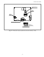
Fig. 1.10
VTM Adjustment (for trucks manufactured earlier than January 31, 2004)
MODE SETTING
SWITCH SW2
White setting
mark
SETTING SWITCH
Upper digit
Lower
digit
Summary of Contents for FB10-7
Page 2: ......
Page 4: ...No SEB 81BBE...
Page 8: ...No SEB 81BBE...
Page 9: ...No SEB 81BBE Fig 1 Overall Dimensions Unit mm in...
Page 10: ...No SEB 81BBE...
Page 28: ...1 BATTERY AND CHARGER 16 NOTE...
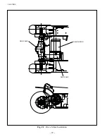
Page 30: ...2 MOTORS 18 DRIVE UNIT Fig 2 1 Drive Motor Installation DRIVE AXLE DRIVE MOTOR...
Page 42: ...3 CONTROL SYSTEM 30 Fig 3 2 Inverter Assembly 1 0 to 2 5 ton Trucks...
Page 43: ...31 3 CONTROL SYSTEM Fig 3 3 Inverter Assembly 3 0 to 3 5 ton Trucks...
Page 44: ...3 CONTROL SYSTEM 32 Fig 3 4 Controller Wiring 1 0 to 2 5 ton Trucks...
Page 45: ...33 3 CONTROL SYSTEM Fig 3 5 Controller Wiring 3 0 to 3 5 ton Trucks...
Page 133: ...7 HYDRAULIC SYSTEM 121 Fig 7 27 Remove the oil seal from the front cover...
Page 160: ...8 LOAD HANDLING SYSTEM 148 NOTE...


