2. MOTORS
- 17 -
2. MOTORS
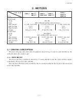
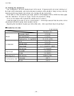
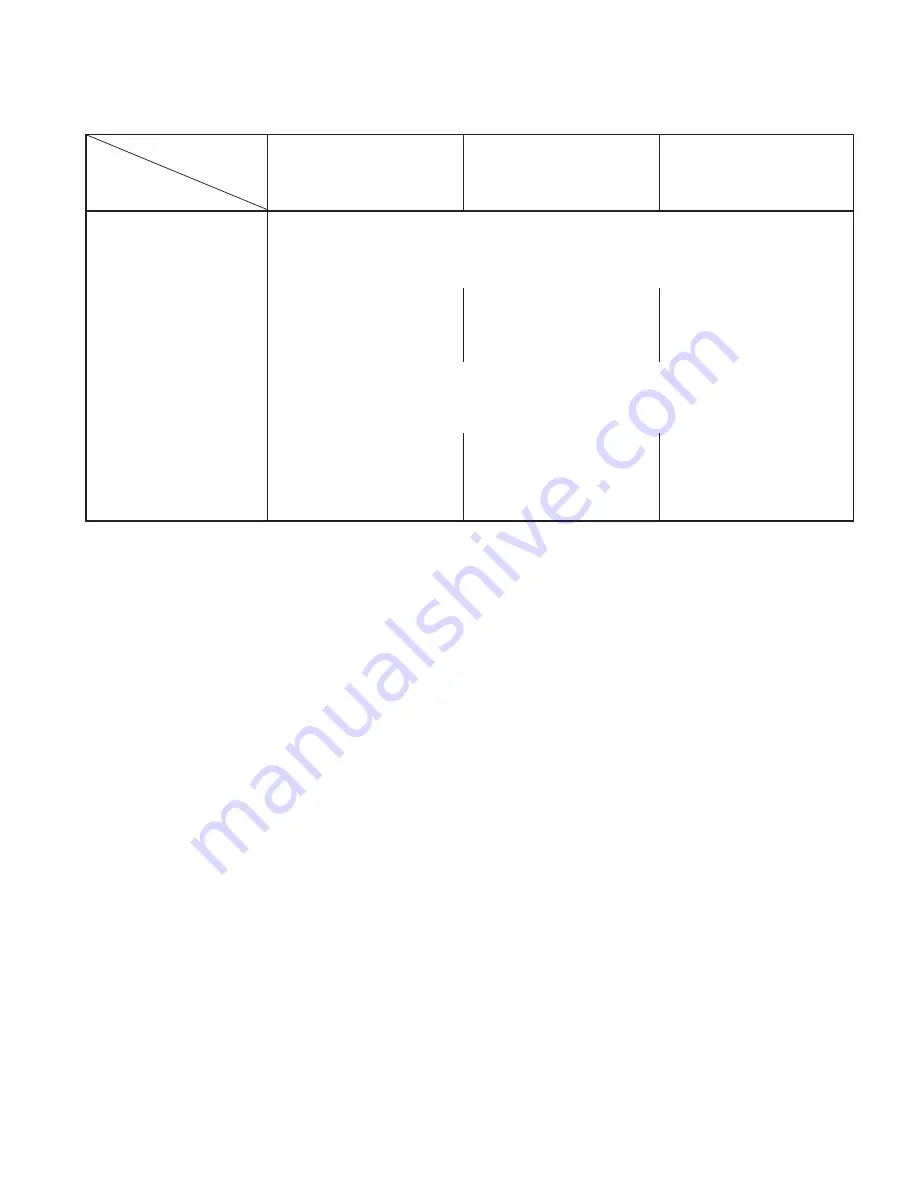
Truck model
FB10-7 FB15-7
FB20-7
FB25-7
FB30-7
FB18-7 FB25-7LB
FB25-7V
FB30-7V
Item
FB35-7S
Drive motor
Name
HO-NR
Type
Self-ventilated, 3-phase induction motor
Rated output
11.5 kW (3-min rate)
13.1 kW (3-min rate)
17.3 kW (3-min rate)
Rated voltage
24.5 V
25.8 V
38 V
Rated current
396 A
425 A
380 A
Weight
60 kg [132.3 lbf]
65 kg [143.3 lbf]
70 kg [154.3 lbf]
Pump motor
Name
HO-MRO-5
Type
Self-ventilated, DC series motor
Rated output
8.6 kW (5-min rate)
9 kW (5-min rate)
14 kW (5-min rate)
Rated voltage
48 V
48 V
68 V
Rated current
260 A
265 A
262 A
Weight
38 kg [83.8 lbf]
45 kg [99.2 lbf]
61 kg [134.5lbf]
2.1 GENERAL DESCRIPTION
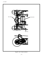
The drive and pump motor are located in positions shown in Figs 2.1 and 2.6, and controlled by the
controller inside the counterweight.
2.1.1 DRIVE MOTOR
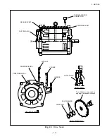
The drive motor has a structure as shown Fig. 2.2 and is installed on the drive unit, with the rotation
controlled by the inverter in the controller.
The rotation of the drive motor is sensed by the two sensors installed in the rear part of the motor and
sent to the controller.
Summary of Contents for FB10-7
Page 2: ......
Page 4: ...No SEB 81BBE...
Page 8: ...No SEB 81BBE...
Page 9: ...No SEB 81BBE Fig 1 Overall Dimensions Unit mm in...
Page 10: ...No SEB 81BBE...
Page 28: ...1 BATTERY AND CHARGER 16 NOTE...
Page 30: ...2 MOTORS 18 DRIVE UNIT Fig 2 1 Drive Motor Installation DRIVE AXLE DRIVE MOTOR...
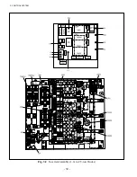
Page 42: ...3 CONTROL SYSTEM 30 Fig 3 2 Inverter Assembly 1 0 to 2 5 ton Trucks...
Page 43: ...31 3 CONTROL SYSTEM Fig 3 3 Inverter Assembly 3 0 to 3 5 ton Trucks...
Page 44: ...3 CONTROL SYSTEM 32 Fig 3 4 Controller Wiring 1 0 to 2 5 ton Trucks...
Page 45: ...33 3 CONTROL SYSTEM Fig 3 5 Controller Wiring 3 0 to 3 5 ton Trucks...
Page 133: ...7 HYDRAULIC SYSTEM 121 Fig 7 27 Remove the oil seal from the front cover...
Page 160: ...8 LOAD HANDLING SYSTEM 148 NOTE...


