2. MOTORS
- 25 -
■
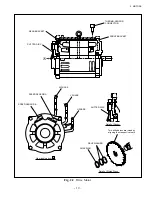
Inspection procedure
Inspect the motors observing the following conditions:
①
Select a place which is not dusty or humid.
②
Parts which have been disassembled should be kept in order and the order of disassembly recorded
to ensure correct reassembly.
Screws and wave washers removed should be put in order in boxes.
③
When removing or reinstalling brackets with a wooden mallet, tap them evenly. Do not use a
metallic hammer.
④
Use caution not to damage parts, especially stator coil and bearings. Exercise caution not to allow
them to collect moisture, dust, or sand.
⑤
Disassembled parts should be cleaned and checked for damage. Any defective parts should be
replaced with new one.
⑥
Do not rub a contaminated coil forcefully. Do not use gasoline, petroleum or solvent for cleaning;
otherwise the insulation will be impaired. Use a dry cloth or soft brush for cleaning.
⑦
If the insulation resistance of the coil is lower than the specified value, dry the coil by heating it to
80 – 90°C [176 – 194°F], avoiding local heating, until the insulation resistance is more than 1 M
Ω
.
⑧
Check bolts for looseness, retightening any loose bolt.
⑨
For the procedure for checking and servicing the bearings, see (4) Maintenance of bearings.
⑩
If the coating is damaged, discolored or exfoliated, apply anti-rust or paint again.
⑪
Tighten the terminals securely. Connections must be completely insulated with insulation tape.
⑫
After reassembly, make sure that there is not any part left and the bolts and screws are securely
tightened. Turn the shaft by hand to make sure it turns smoothly. Run the motor on a trial basis.
⑬
The motor should be stored in a dry, clean place free from alkaline or other harmful gases. The shaft
should be applied with anti-rust and covered with oilpaper or vinyl sheet.
Summary of Contents for FB10-7
Page 2: ......
Page 4: ...No SEB 81BBE...
Page 8: ...No SEB 81BBE...
Page 9: ...No SEB 81BBE Fig 1 Overall Dimensions Unit mm in...
Page 10: ...No SEB 81BBE...
Page 28: ...1 BATTERY AND CHARGER 16 NOTE...
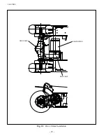
Page 30: ...2 MOTORS 18 DRIVE UNIT Fig 2 1 Drive Motor Installation DRIVE AXLE DRIVE MOTOR...
Page 42: ...3 CONTROL SYSTEM 30 Fig 3 2 Inverter Assembly 1 0 to 2 5 ton Trucks...
Page 43: ...31 3 CONTROL SYSTEM Fig 3 3 Inverter Assembly 3 0 to 3 5 ton Trucks...
Page 44: ...3 CONTROL SYSTEM 32 Fig 3 4 Controller Wiring 1 0 to 2 5 ton Trucks...
Page 45: ...33 3 CONTROL SYSTEM Fig 3 5 Controller Wiring 3 0 to 3 5 ton Trucks...
Page 133: ...7 HYDRAULIC SYSTEM 121 Fig 7 27 Remove the oil seal from the front cover...
Page 160: ...8 LOAD HANDLING SYSTEM 148 NOTE...

