- 29 -
3. CONTROL SYSTEM
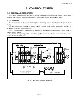
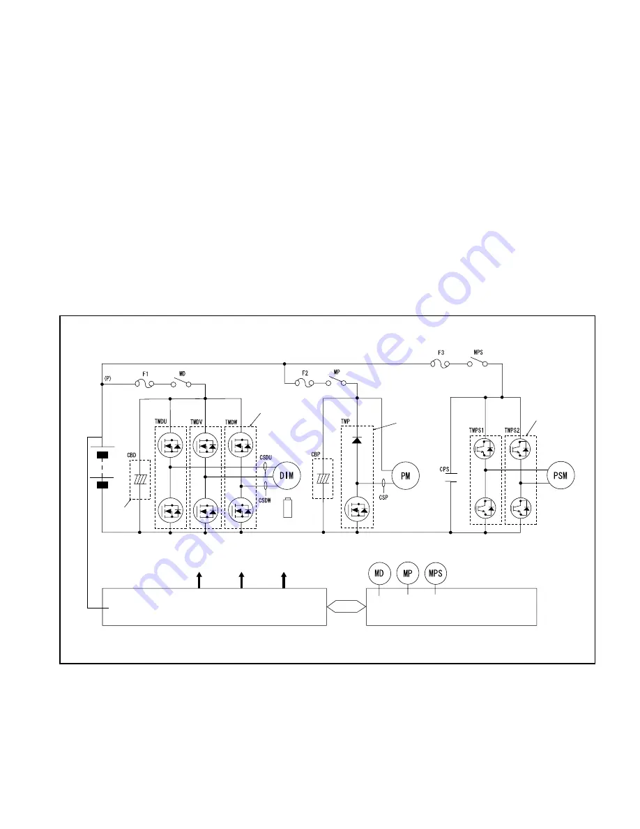
Fig. 3.1
Schematic Diagram of Inverter
3. CONTROL SYSTEM
3.1 GENERAL DESCRIPTION
The control system consists primarily of an inverter assembly which controls the drive motor, a DC
chopper which controls the pump motor, and a PS controller which controls the PS motor.
3.1.1 INVERTER
The inverter converts direct current into 3-phase alternating current. Its schematic diagram is shown
in Fig. 3.1
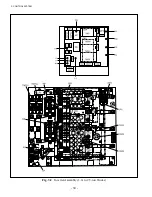
The inverter consists primarily of a CPU board, a power supply board, and an FET module. Its
schematic diagram is shown in Fig. 3.2.
The CPU board receives signals from the accelerator and others to control the drive motor using the
inverter’s FET module.
The drive motor operating status is monitored by the speed sensor, thermo sensor, and current sensor
and fed back to the CPU board.
POWER MODULE
(3 pcs.)
BATTERY
DRIVE
MOTOR
SPEED SENSOR
POWER
MODULE (1 pc.)
PUMP
MOTOR
POWER
MODULE (2 pcs.)
TMD
GATE
TMP GATE
TMPS
GATE
POWER SUPPLY/GATE
DRIVE BOARD
32-BIT CPU BOARD
CAPACITOR
BOARD
Summary of Contents for FB10-7
Page 2: ......
Page 4: ...No SEB 81BBE...
Page 8: ...No SEB 81BBE...
Page 9: ...No SEB 81BBE Fig 1 Overall Dimensions Unit mm in...
Page 10: ...No SEB 81BBE...
Page 28: ...1 BATTERY AND CHARGER 16 NOTE...
Page 30: ...2 MOTORS 18 DRIVE UNIT Fig 2 1 Drive Motor Installation DRIVE AXLE DRIVE MOTOR...
Page 42: ...3 CONTROL SYSTEM 30 Fig 3 2 Inverter Assembly 1 0 to 2 5 ton Trucks...
Page 43: ...31 3 CONTROL SYSTEM Fig 3 3 Inverter Assembly 3 0 to 3 5 ton Trucks...
Page 44: ...3 CONTROL SYSTEM 32 Fig 3 4 Controller Wiring 1 0 to 2 5 ton Trucks...
Page 45: ...33 3 CONTROL SYSTEM Fig 3 5 Controller Wiring 3 0 to 3 5 ton Trucks...
Page 133: ...7 HYDRAULIC SYSTEM 121 Fig 7 27 Remove the oil seal from the front cover...
Page 160: ...8 LOAD HANDLING SYSTEM 148 NOTE...

