- 35 -
3.1.3 INTERLOCK SYSTEM
The interlock system is a safety device that cuts off power supply to the drive or hydraulic motor
when the operator gets out of the seat during operation.
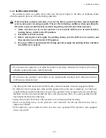
If the interlock system is activated, you won’t be able to operate the drive system, hydraulic
system, and power steering properly. Observe the following conditions when operating the
lift truck to prevent the interlock system from getting activated more than necessary.
1. Make sure that you are in the operator’s seat and the shift lever is in neutral before
turning the key switch to the ON position.
2. Fasten the seat belt securely.
3. Before leaving the truck, apply the parking brakes, put the shift lever in neutral, and
then turn the key switch to the OFF position.
4. If you get off the truck temporarily during operation, apply the parking brakes and place
the shift lever in neutral.
• Do not leave the operator’s seat while the forks are lowering; otherwise the forks stop lowering
abruptly, causing the load to fall off the forks.
• Do not leave the operator’s seat while you are operating the steering wheel; otherwise steering
will become extremely hard.
• The driving interlock system only shifts the drive unit into neutral; it doesn’t engage the brakes.
• If, while the truck is going up a ramp and the operator leaves the seat or stands up, or if the truck
is operated from a position that does not press the operator’s body weight on the seat, the driving
interlock will be activated and shift the drive unit into neutral. Then, it is quite possible that the
truck might roll back down the slope.
• Fasten the seat belt. Don’t leave the operator’s seat or stand up while traveling.
• Don’t rest anything heavy on the operator’s seat; otherwise the driving interlock may fail to
operate as it should.
• If the operator’s seat is replaced with a new one, use a genuine TCM operator’s seat equipped
with a seat switch.
3. CONTROL SYSTEM
Summary of Contents for FB10-7
Page 2: ......
Page 4: ...No SEB 81BBE...
Page 8: ...No SEB 81BBE...
Page 9: ...No SEB 81BBE Fig 1 Overall Dimensions Unit mm in...
Page 10: ...No SEB 81BBE...
Page 28: ...1 BATTERY AND CHARGER 16 NOTE...
Page 30: ...2 MOTORS 18 DRIVE UNIT Fig 2 1 Drive Motor Installation DRIVE AXLE DRIVE MOTOR...
Page 42: ...3 CONTROL SYSTEM 30 Fig 3 2 Inverter Assembly 1 0 to 2 5 ton Trucks...
Page 43: ...31 3 CONTROL SYSTEM Fig 3 3 Inverter Assembly 3 0 to 3 5 ton Trucks...
Page 44: ...3 CONTROL SYSTEM 32 Fig 3 4 Controller Wiring 1 0 to 2 5 ton Trucks...
Page 45: ...33 3 CONTROL SYSTEM Fig 3 5 Controller Wiring 3 0 to 3 5 ton Trucks...
Page 133: ...7 HYDRAULIC SYSTEM 121 Fig 7 27 Remove the oil seal from the front cover...
Page 160: ...8 LOAD HANDLING SYSTEM 148 NOTE...


