3. CONTROL SYSTEM
- 36 -
○
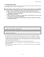
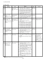
The key switch is turned to ON when the operator is not in the operator’s seat.
■
The interlock system is activated if any of the following conditions occurs.
Operation of the truck
Traction Pump Power
steering
Blinks
(Stays on if parking brake lever is pulled.)
Blinks
is displayed
An alarm buzzer will sound for
one half second if the parking
brake lever is in released position.
Blinks
(Stays on if parking brake lever is
pulled. No buzzer sounds.)
Within
3 seconds
How to release:
The interlock will be released by sitting down again within 6 seconds
after the truck comes to a stop (or within 9 seconds after leaving the
seat).
If more than 6 seconds (after the truck comes to a stop) or 9 seconds
(after leaving the seat) passes, you must sit down and place the shift
lever and the load handling levers into neutral to release the interlock.
3 seconds
passed
○
The operator leaves the operator’s seat when the key switch is in the
ON position.
×
×
×
○
○
○
×
×
×
How to release:
Turn the key switch to OFF, sit down and turn the key switch to ON.
“
” will be displayed and the “ N ” mark will blink if the
operator performs any operation other than turning the steering wheel
or shifting the lift lever in the lowering phase (when the shift lever is
not in neutral.)
3.1.4 BACK-DOWN ALARM SYSTEM
Alarm
•
If the accelerator pedal is released while the truck is going up a hill in forward, the truck might stop
and then back down the slope. In this case, the anti-roll-off regeneration function will be activated to
cause the backup buzzer to sound, even if the shift lever is in the forward position.
How to release the alarm
•
Press the accelerator pedal to release the anti-roll-off regeneration function and the buzzer will stop.
(CAUTION)
•
Do not place the shift lever in neutral on a slope — the truck might back down the slope rapidly.
Summary of Contents for FB10-7
Page 2: ......
Page 4: ...No SEB 81BBE...
Page 8: ...No SEB 81BBE...
Page 9: ...No SEB 81BBE Fig 1 Overall Dimensions Unit mm in...
Page 10: ...No SEB 81BBE...
Page 28: ...1 BATTERY AND CHARGER 16 NOTE...
Page 30: ...2 MOTORS 18 DRIVE UNIT Fig 2 1 Drive Motor Installation DRIVE AXLE DRIVE MOTOR...
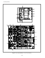
Page 42: ...3 CONTROL SYSTEM 30 Fig 3 2 Inverter Assembly 1 0 to 2 5 ton Trucks...
Page 43: ...31 3 CONTROL SYSTEM Fig 3 3 Inverter Assembly 3 0 to 3 5 ton Trucks...
Page 44: ...3 CONTROL SYSTEM 32 Fig 3 4 Controller Wiring 1 0 to 2 5 ton Trucks...
Page 45: ...33 3 CONTROL SYSTEM Fig 3 5 Controller Wiring 3 0 to 3 5 ton Trucks...
Page 133: ...7 HYDRAULIC SYSTEM 121 Fig 7 27 Remove the oil seal from the front cover...
Page 160: ...8 LOAD HANDLING SYSTEM 148 NOTE...


