- 41 -
3. CONTROL SYSTEM
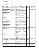
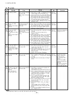
No.
86
[501]
87
88
[106]
[105]
91
[502]
Problem
Load dump error
Seat switch not detected.
* This error code might
also occur due to an
improper operation.
Traveling speed over the
limit
* This error code might
also occur when the
truck speed reaches
around 18.2 km/h. (3 t:
16.8 km/h) This is not
a problem.
Error
Neither traveling or load
handling system does
not function.
The truck won’t move.
The truck moves
normally.
(This error code might
be displayed when the
truck speed reaches 18.2
km/h, but it disappears
when the truck slows
down below 16.2 km/h.
(3 t: 14.6 km/h) While
the error is detected, the
current is restricted and
output drops.)
Remedy
Proceed with remedy in numerical order of encircled numbers.
①
Check battery connectors and connection
harness, and repair if needed.
②
Check harness between P terminal and battery
connector and harness between N terminal
and battery connector, and repair or change if
needed.
③
Check P and N terminals for looseness, and
retighten if needed.
④
Check traveling contactor (see error code 04).
⑤
Check load handling contactor (see error code
33).
⑥
Check contactor drive Tr (see error codes 07
and 38).
⑦
Check traveling/load handling fuses (see error
codes 20 and 45).
①
Turn on seat switch and place accelerator and
F/R direction switch in neutral.
②
Check seat switch for opening, and repair or
change if needed.
③
Check accelerator or direction switch for
shorting, and repair or change if needed.
④
Check circuit connectors for looseness and
harnesses, and repair or change if needed.
①
Check harness between CN2-3, 4 (CPU board)
and traveling speed sensor A, and repair or
change if needed.
②
Check harness between CN11-5, 6 (CPU
board) and traveling sensor B, and repair or
change if needed.
③
Check traveling sensor A and B, and repair or
change if needed.
④
Change traveling motor. (The engagement of
sensor and slit plate inside motor is improper.)
Reset
Restore to
normal.
Turn on
seat switch,
and turn off
accelerator
and F/R
switch.
Restore to
normal.
Remarks
Power module bridge
voltage rises excessively.
Numbers in brackets are error codes that appear on the meter panel.
Summary of Contents for FB10-7
Page 2: ......
Page 4: ...No SEB 81BBE...
Page 8: ...No SEB 81BBE...
Page 9: ...No SEB 81BBE Fig 1 Overall Dimensions Unit mm in...
Page 10: ...No SEB 81BBE...
Page 28: ...1 BATTERY AND CHARGER 16 NOTE...
Page 30: ...2 MOTORS 18 DRIVE UNIT Fig 2 1 Drive Motor Installation DRIVE AXLE DRIVE MOTOR...
Page 42: ...3 CONTROL SYSTEM 30 Fig 3 2 Inverter Assembly 1 0 to 2 5 ton Trucks...
Page 43: ...31 3 CONTROL SYSTEM Fig 3 3 Inverter Assembly 3 0 to 3 5 ton Trucks...
Page 44: ...3 CONTROL SYSTEM 32 Fig 3 4 Controller Wiring 1 0 to 2 5 ton Trucks...
Page 45: ...33 3 CONTROL SYSTEM Fig 3 5 Controller Wiring 3 0 to 3 5 ton Trucks...
Page 133: ...7 HYDRAULIC SYSTEM 121 Fig 7 27 Remove the oil seal from the front cover...
Page 160: ...8 LOAD HANDLING SYSTEM 148 NOTE...


