4. DRIVE UNIT AND DRIVE AXLE
- 59 -
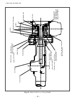
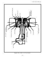
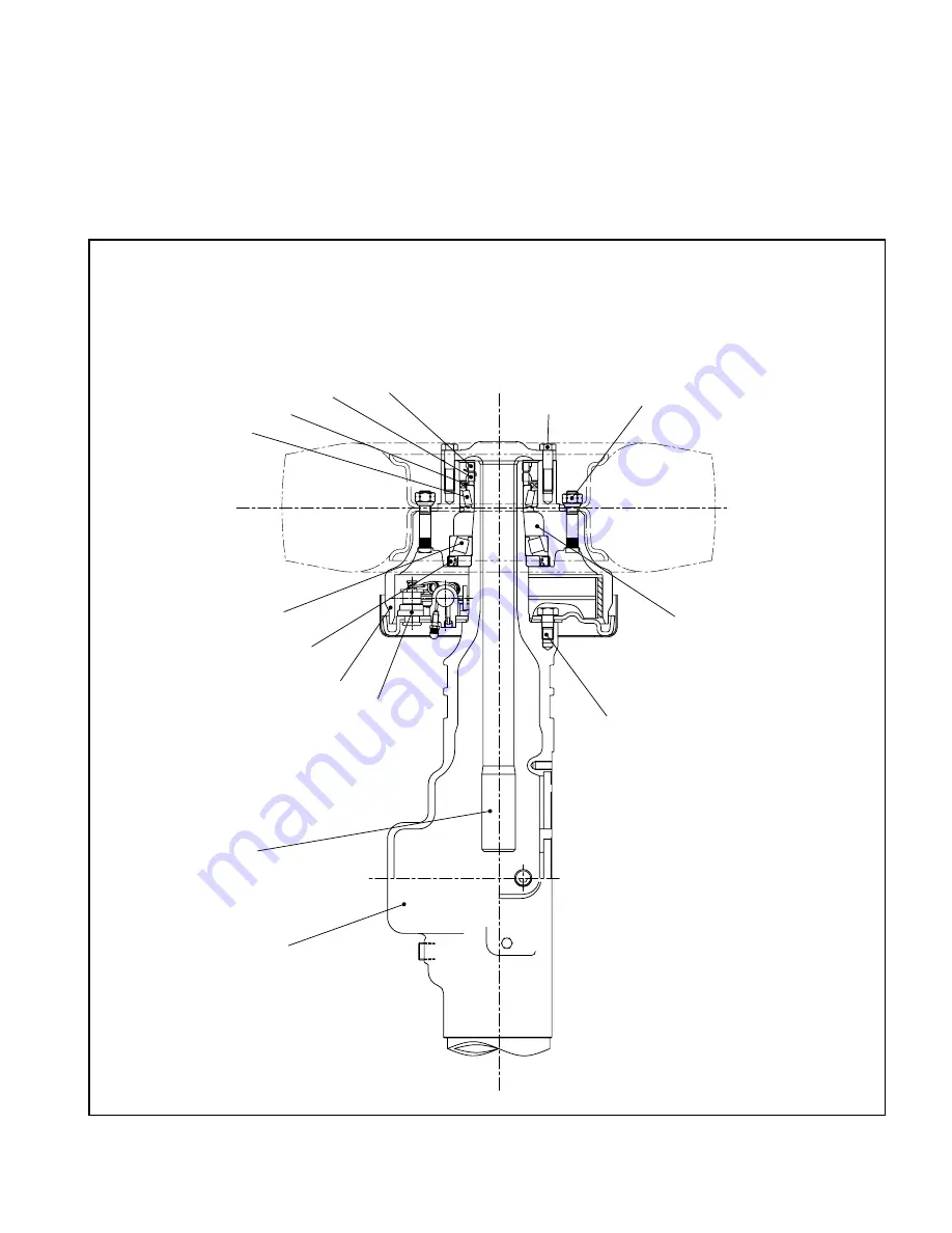
4.1.2 DRIVE AXLE
The drive axle is composed of an axle housing, wheel hub, and wheels. It is mounted at the front side
of the frame.
At each end of the axle housing are a wheel hub and a wheel brake.
The wheel hub is supported on the spindle by two taper roller bearings, and is driven by the axle
shaft.
Fig. 4.4
Drive Axle (1- to 1.8-ton Trucks)
TAPERED ROLLER BEARING
OIL
SEAL
ADJUSTMENT
NUT
LOCK NUT
Tightening torque: 98 to 1
13 N-m
{1000 to 1
150 kgf-cm}
[870 to 1000 lbf-in.] (Apply LOCTITE#262)
Tightening torque: 150 to 175 N-m {1530 to 1780 kgf-cm} [1330 to 1550 lbf-in.]
TAPERED ROLLER
BEARING
OIL
SEAL
HUB & BRAKE DRUM
WHEEL
BRAKE
AXLE SHAFT
AXLE HOUSING
Tightening torque:
120 to 140 N-m
{1220 to 1430 kgf-cm}
[ 1060 to 1240 lbf-in.]
(Apply LOCTITE#270
Fill 50% of the space with grease (100 cc at one side)
Summary of Contents for FB10-7
Page 2: ......
Page 4: ...No SEB 81BBE...
Page 8: ...No SEB 81BBE...
Page 9: ...No SEB 81BBE Fig 1 Overall Dimensions Unit mm in...
Page 10: ...No SEB 81BBE...
Page 28: ...1 BATTERY AND CHARGER 16 NOTE...
Page 30: ...2 MOTORS 18 DRIVE UNIT Fig 2 1 Drive Motor Installation DRIVE AXLE DRIVE MOTOR...
Page 42: ...3 CONTROL SYSTEM 30 Fig 3 2 Inverter Assembly 1 0 to 2 5 ton Trucks...
Page 43: ...31 3 CONTROL SYSTEM Fig 3 3 Inverter Assembly 3 0 to 3 5 ton Trucks...
Page 44: ...3 CONTROL SYSTEM 32 Fig 3 4 Controller Wiring 1 0 to 2 5 ton Trucks...
Page 45: ...33 3 CONTROL SYSTEM Fig 3 5 Controller Wiring 3 0 to 3 5 ton Trucks...
Page 133: ...7 HYDRAULIC SYSTEM 121 Fig 7 27 Remove the oil seal from the front cover...
Page 160: ...8 LOAD HANDLING SYSTEM 148 NOTE...


