5. BRAKE SYSTEM
- 73 -
5.2.2 INSPECTION
Check each part and repair or replace any defective one.
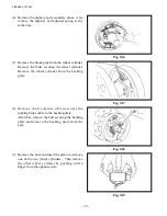
(1) Check the wheel cylinder inner surface and
piston outer periphery for rust.
Measure the clearance between the piston and
cylinder.
Standard: 0.03 to 0.10 mm
[0.0012 to 0.0039 in.]
Limit:
0.15 mm [0.0059 in.]
Fig. 5.20
Fig. 5.21
Fig. 5.22
(2) Visually check the piston cup for damage or deformation and replace any damaged or deformed
one.
(3) Measure the free length of the wheel cylinder spring. If the length is out of the standard value,
replace the spring.
(4) Measure the brake lining thickness and replace
any excessively worn lining.
Unit: mm [in.]
1.0 – 1.8 t
2.0 – 3.5 t
Standard
4.87 [0.192]
7.67 [0.302]
Limit
2.5 [0.098]
5.0 [0.197]
(5) Visually check the inner surface of the
brake drum. If any damage or uneven wear
is observed, grind it to repair. Replace an
excessively damaged or worn drum.
Unit: mm [in.]
1.0 – 1.8 t
2.0 – 2.5 t 3.0 – 3.5 t
Standard
254 [10]
310 [12.20] 314 [12.36]
Limit
256 [10.1] 312 [12.28] 316 [12.44]
Summary of Contents for FB10-7
Page 2: ......
Page 4: ...No SEB 81BBE...
Page 8: ...No SEB 81BBE...
Page 9: ...No SEB 81BBE Fig 1 Overall Dimensions Unit mm in...
Page 10: ...No SEB 81BBE...
Page 28: ...1 BATTERY AND CHARGER 16 NOTE...
Page 30: ...2 MOTORS 18 DRIVE UNIT Fig 2 1 Drive Motor Installation DRIVE AXLE DRIVE MOTOR...
Page 42: ...3 CONTROL SYSTEM 30 Fig 3 2 Inverter Assembly 1 0 to 2 5 ton Trucks...
Page 43: ...31 3 CONTROL SYSTEM Fig 3 3 Inverter Assembly 3 0 to 3 5 ton Trucks...
Page 44: ...3 CONTROL SYSTEM 32 Fig 3 4 Controller Wiring 1 0 to 2 5 ton Trucks...
Page 45: ...33 3 CONTROL SYSTEM Fig 3 5 Controller Wiring 3 0 to 3 5 ton Trucks...
Page 133: ...7 HYDRAULIC SYSTEM 121 Fig 7 27 Remove the oil seal from the front cover...
Page 160: ...8 LOAD HANDLING SYSTEM 148 NOTE...


