6. STEERING SYSTEM
- 83 -
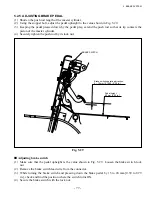
Adjusting the position of the combination switch angle sensor
1. Put the rear wheels in the straight-ahead position.
2. Align the intersection of the two equal sides of a triangle formed by the three vortexes (
☆
) at the combination
switch side, with the front of the truck.
3. Engage the vertexes (
☆
) of the combination switch with the concaves (*) of the steering handwheel.
Fig. 6.4
Steering Handwheel
F/R LEVER
LIGHTING SWITCH
STEERING
HANDWHEEL
ASSEMBLY
Front of
the truck
COMBINATION
SWITCH ASSEMBLY
STEERING SHAFT
ASSEMBLY
Front of the truck
Front of the truck
Assembly drawing
View looking from C
View looking from A
View looking from B
Summary of Contents for FB10-7
Page 2: ......
Page 4: ...No SEB 81BBE...
Page 8: ...No SEB 81BBE...
Page 9: ...No SEB 81BBE Fig 1 Overall Dimensions Unit mm in...
Page 10: ...No SEB 81BBE...
Page 28: ...1 BATTERY AND CHARGER 16 NOTE...
Page 30: ...2 MOTORS 18 DRIVE UNIT Fig 2 1 Drive Motor Installation DRIVE AXLE DRIVE MOTOR...
Page 42: ...3 CONTROL SYSTEM 30 Fig 3 2 Inverter Assembly 1 0 to 2 5 ton Trucks...
Page 43: ...31 3 CONTROL SYSTEM Fig 3 3 Inverter Assembly 3 0 to 3 5 ton Trucks...
Page 44: ...3 CONTROL SYSTEM 32 Fig 3 4 Controller Wiring 1 0 to 2 5 ton Trucks...
Page 45: ...33 3 CONTROL SYSTEM Fig 3 5 Controller Wiring 3 0 to 3 5 ton Trucks...
Page 133: ...7 HYDRAULIC SYSTEM 121 Fig 7 27 Remove the oil seal from the front cover...
Page 160: ...8 LOAD HANDLING SYSTEM 148 NOTE...

