program
setup
program
setup
program
setup
program
setup
program
setup
program
setup
MON
12:00 AM 72F
56.
SET ACCESS
CODE: 000
55.
REQUIRE CODE FOR
CLOCK / SCHED? YES
54.
YE
S
RECOVERY
?
REQUIRE CODE FOR
PROGRAMMING? YES
53.
60
SECONDS
ENABLE SMART
RECOVERY? YES
DI3 USED FOR:
FILTER
SERVICE
52.
DELAY ON POWERUP
60 SECONDS
FILTER
SERVICE
51.
DI3 USED FOR:
FILTER SERVICE
program
setup
FILTER
SERVICE
SET DI2 SETPOINT
SHIFT: 02F
57.
R
2800 LAURA LANE • MIDDLETON, WI 53562 • (800) 288-9383 • FAX (608) 836-9044 • www.tcsbasys.com
7
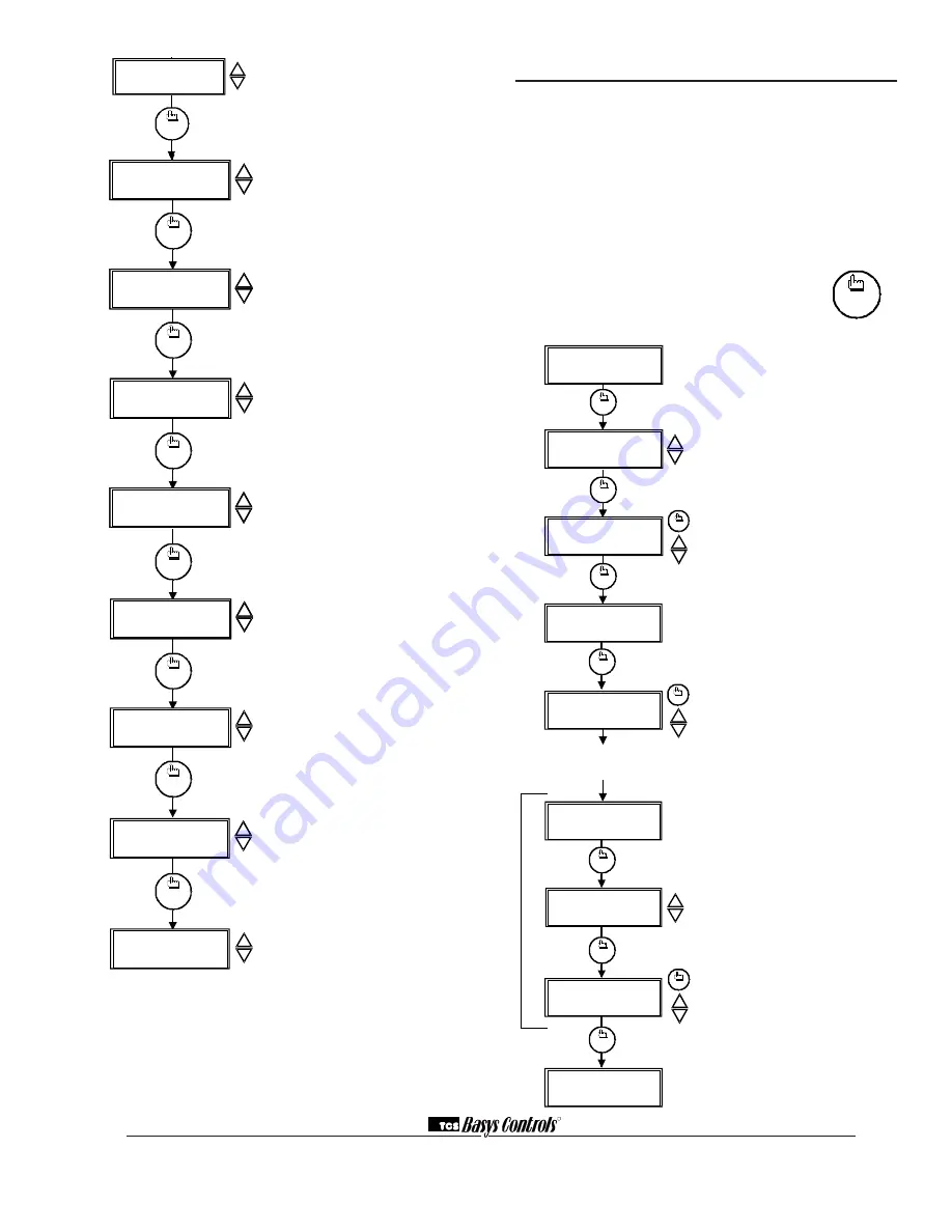
DI2 Choice Screen.
Choose DI2 as
SERVICE, AQUASTAT, or MONITOR.
Select MONITOR if unused.
DI2 Shift Screen.
Enter the setpoint
shift value. This screen will only appear
if DI2 is set to MONITOR.
DI3 Choice Screen.
Choose FILTER
SERVICE, EXTernal OVERRIDE,
or EXTernal TIME CLOCK. Select
FILTER SERVICE if unused.
Delay On Powerup Screen.
Enter a
value in seconds, such that when the
unit is powered up, no control starts for
this amount of time.
Smart Recovery Screen.
Choose
whether or not smart recovery will be
used.
Note: Smart Recovery is not
available when DI3 is used as EXTernal
TIME CLOCK.
Programming Access Screen.
Choose
whether or not a code will be required
to enter programming setup. A dipswitch
option to lock out access altogether is also
available.
Clock and Schedule Access Screen.
Choose whether or not a code will be
required to enter clock and schedule
setup. A dipswitch option to lock out
access altogether is also available.
Access Code Screen.
Enter an access (0
to 255) code that will be used to enter the
programming and/or clock and schedule
setups if access code has been required in
the last two steps. The default is 248.
Main Monitoring Screen.
Setting Clock & Schedule
The SZ1018 clock and schedule may be set through
the keypad on the face, or with a PC. For more infor-
mation on programming through the PC, consult your
software manual.
SETTING CLOCK & SCHEDULE
THROUGH THE KEYPAD
To access the clock and schedule screens, press the
clock setup button. To make changes, use the warmer
and cooler keys. For screens that have more
than one field to set, use the override key
to move to the next field. Access may be
locked out with dipswitches, or an access
code may be required.
clock
setup
Main Monitoring Screen.
Press the
service button to access the following
screens.
Access Code Entry Screen.
May
appear if access code is required for
setting clock and schedules. Use 248
as the default. If the wrong code is
entered, it will revert to the previous
screen.
Time and Day Screen.
Set the hour,
minutes, AM or PM, and day of the
week.
Schedule Announcement Screen.
Announces the next screen.
Occupied Times Screen.
Set hours
and minutes of start and end times for
up to two occupied periods.
Schedule Announcement Screen.
Announces the next screen.
Copy Schedule Screen.
Choose to
use the same schedule that was used
for the previous day. If so, the next
screen does not appear.
Occupied Times Screen.
Set hours
or minutes of start and end times for
up to two occupied periods.
Main Monitoring Screen.
MON
72F
12:00 AM
3.
1.
clock
setup
ENTER ACCESS
SET TIME & DAY:
MON
12:00 AM
2.
000
CODE
override
clock
setup
clock
setup
SET OCCUPIED
A:08:00 TO 12:00
4.
5.
TIMES MONDAY:
B:13:00 TO 17:00
SET OCCUPIED
6.
TIMES TUESDAY:
The following screens are repeated for
Wednesday, Thursday, Friday, Saturday
and Sunday.
COPY MON FOR
TUE? YES
7.
MON
72F
12:00 AM
A:08:00 TO 12:00
B:13:00 TO 17:00
clock
setup
override
clock
setup
clock
setup
clock
setup
override
program
setup
program
setup
program
setup
program
setup
program
setup
program
setup
program
setup
program
setup
50.
DI2 USED FOR:
SERVICE
49.
48.
DI1 USED FOR
FAN PROVING
HEATING LOCKOUT
TEMP: 70F
47.
COOLING LOCKOUT
46.
TEMP: 80F
ENABLE OUTDOOR
AIR SENSOR? YES
45.
RESET RATIO
44.
FACTOR: 2F
DISCHARGE AIR
SETPOINT: 90F
42.
CONTROL BASED
ON: SPACE
DISCHARGE AIR
HIGH LIMIT: 120F
program
setup
program
setup
43b.
ENABLE HEATING
LOW LIMIT? YES
43a.


