air temperature rises 2° above the lockout temperature. If
the outdoor temperature rises above the HEATING LOCK-
OUT TEMP, all heating stages will be locked out and will
remain locked out until the outdoor air temperature falls 2°
below the lockout temperature.
The outdoor air span is -40 to 160 °F (-40.0 to 71.1 °C).
FAN PROVING
The SZ1017N allows DI1 to be set for fan proving to pro-
tect equipment on fan failure. To utilize this, a pressure or
current switch is required, which indicates when the fan is
running. If the thermostat turns on the FAN, and DI1 is not
closed after thirty seconds, the system will go to OFF, dis-
abling all outputs, the fan LED will turn off, and the service
LED will be lit until the system is manually reset by
switching the system to a mode other than OFF.
DI2 SETPOINT SHIFT
The SZ1017N allows DI2 to be set for setpoint shift for
energy demand setback. This is enabled by setting DI2 to
the MONITOR mode. A digital contact that closes when
setback is needed should be wired into DI2. You may speci-
fy a number of degrees such that, when the thermostat is
operating in the occupied mode, and DI2 is closed, the
heating setpoint will be lowered this number of degrees,
and the cooling setpoint will be raised this number of
degrees. The fan will continue to operate according to its
occupied setting. If you are using DI2 as monitor for anoth-
er purpose, make sure to set the setpoint and shift value to
zero.
STAGE OUTPUT PARAMETERS
The SZ1017N will control up to two stages of either heat-
ing or cooling.
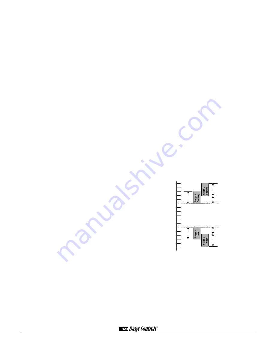
For each stage, you may specify an offset and a differential
value. The offset value is the amount away from the set-
point a stage will turn off. By assigning a stage a value
other than zero, you “anticipate” that the residual heat or
cooling in the duct or the other stages will bring the tem-
perature back to setpoint. In most cases, the first stage is set
to zero. The differential value is the difference between the
on and off points.
DISCHARGE AIR TEMPERATURE SENSING
The SZ1017N accepts a remote 1000
Ω
discharge air sensor
(TS1009 or TS1002) for monitoring purposes. (See setup
instructions for dipswitch placement for this option.)
Choose YES in programming screen #28 only if you are
using a discharge air sensor and you want to enable the dis-
charge air temperature high and low limit functions or dis-
charge air reset function. See Discharge Air Reset section
for further programming options. If NO is chosen, the dis-
charge air is still monitored.
When the function is enabled, a LOW LIMIT and HIGH
LIMIT are entered in steps #29 and #30. If the HIGH
LIMIT is reached, the fan and heating stages will be turned
off and will remain off until the discharge air temperature
falls 3° below that limit. If the LOW LIMIT is reached, the
fan and cooling stages will be turned off and will remain off
until the discharge air rises 3° above that limit. When either
limit is reached, the service LED will be on until normal
operation resumes.
The discharge air span is 0 to 150 °F (-17.8 to 65.6 °C).
ANALOG OUTPUT / DISCHARGE AIR RESET
The analog output on the SZ1017N is used to control the
heating or cooling in a space. To use the discharge air reset
function, a discharge air sensor must be installed. In pro-
gramming step #28, the discharge air sensor must be
enabled. In programming step #31, the control must be
based on DISCHARGE air.
In programming screen #32, you are asked to enter a dis-
charge air setpoint. The discharge air temperature will be
controlled to this setting by modulating the heating or cool-
ing device.
In programming screen #33, you are asked to enter a reset
ratio factor. This is the number of degrees that the dis-
charge air setpoint is raised when the room temperature falls
below the heating setpoint by 1 degree if the analog output
is set for heating, or the number of degrees that the dis-
charge air setpoint is lowered when the room temperature
rises above the cooling setpoint by 1 degree if the analog
output is set for cooling.
OUTDOOR AIR TEMPERATURE SENSING
The SZ1017N accepts a remote 1000
Ω
outdoor tempera-
ture sensor (TS1003) for monitoring purposes. (See setup
instructions for dipswitch placement for this option.)
Choose YES in programming screen #34 only if you are
using an outdoor air sensor and you want to enable the out-
door air heating and cooling lockout functions. If NO is
chosen, the outdoor air is still monitored.
When the function is enabled, a COOLING LOCKOUT
TEMP and HEATING LOCKOUT TEMP are entered in
steps #35 and #36. If the outdoor temperature falls below
the COOLING LOCKOUT TEMP, all cooling stages will
be locked out and will remain locked out until the outdoor
Heat Setpoint
Cool Setpoint
ON
ON
ON
ON
OFF
OFF
OFF
OFF
Differential
Differential
Offset
Offset
Differential
Differential
R
2800 LAURA LANE
I
MIDDLETON, WI 53562
I
(800) 288-9383
I
FAX (608) 836-9044
I
www.tcs-basys.com
8


