background image

R

2800 LAURA LANE • MIDDLETON, WI 53562 •  (800) 288-9383 • FAX (608) 836-9044 • www.tcsbasys.com

1

        Communicating Thermostats

        Communicating Thermostats

SZ1022/SZ1031/SZ1035/

Conventional Heating & Cooling 

Thermostats

Product Manual          

Description                             

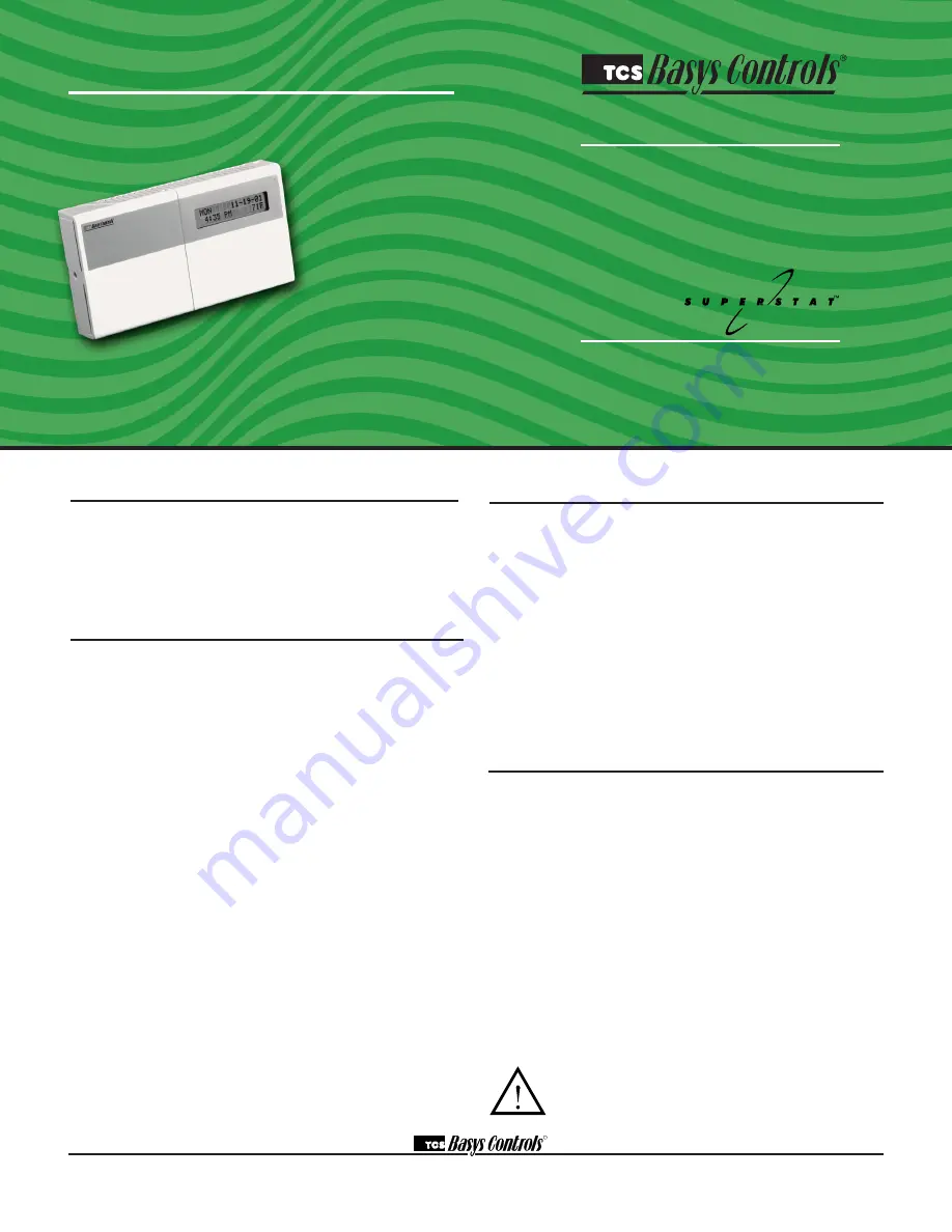
The SZ1022, SZ1031, and SZ1035, are microprocessor-

based programmable thermostats designed for conven-

tional heating and cooling applications. The SZ1022 

features a 7-day time clock, while the SZ1031 and 

SZ1035 feature a 365-day time clock. 

Features                                 

•   Stand-alone or network operation

•   Adjustable delay on power-up and start-up for soft 

starts

•   P+I control option

•  Smart Recovery

•   No battery backup required

•   Built-in HVAC equipment protection

•   32 character LCD display

•   6 status LEDs

•   Remote room sensing capability

•   User setpoint adjustment limits

•   Local and remote override capability 

•   System and fan switching with access lockouts

•   Auxiliary time clock output (economizers) 

•   Equipment monitoring inputs and indication

•   External time clock input 

•   Access to programming or schedule may be locked 

out or limited with the use of an access code

•  Fahrenheit or Celsius temperature display

•   Uses ZigBee protocol, IEEE 802.15.4 compliant*

•   Self-healing, "plug & play" mesh network*

•   100mW output at 2.4 GHz*

•  150 to 500 feet typical in building range*

* wireless devices only

Contents                                  

Description

 . . . . . . . . . . . . . . . . . . . . . . . . . . . . . . . . . .

1

Features

. . . . . . . . . . . . . . . . . . . . . . . . . . . . . . . . . . . .

1

Mounting. . . . . . . . . . . . . . . . . . . . . . . . . . . . . . . . . . . .

1

Wiring

. . . . . . . . . . . . . . . . . . . . . . . . . . . . . . . . . . . . . .

2

Setup

  . . . . . . . . . . . . . . . . . . . . . . . . . . . . . . . . . . . . . . 3

Programming

 . . . . . . . . . . . . . . . . . . . . . . . . . . . . . . . . 4

Setting Clock & Schedule

. . . . . . . . . . . . . . . . . . . . . . . 7

Program Options & Operating Features

. . . . . . . . . . . .

8

Checkout & Troubleshooting

  . . . . . . . . . . . . . . . . . . . .

10

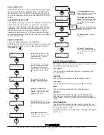
LED Description

. . . . . . . . . . . . . . . . . . . . . . . . . . . . . .

12

User’s Guide

. . . . . . . . . . . . . . . . . . . . . . . . . . . . . . . . .

12

Mounting                                 

The SZ1022, SZ1031, and SZ1035 are designed for wall 

mounting using two #6-32 machine screws sheet metal 

screws, either over a horizontally installed 2” x 4” junc-

tion box, or directly to block or drywall. 

For best results, the thermostat should be mounted on 

an interior wall which reflects normal room environment, 

at a height of approximately five feet from the floor. 

Avoid areas exposed to direct sunlight, unusual heat 

or cool sources, open doors and windows, unventilated 

locations and hot or cold air from diffusers.
If using a remote room sensor, it should be mounted in 

the manner described above.  The thermostat may then 

be mounted in an area which is accessible for adjusting 

its settings. 

Caution

:  Remove power from thermostat prior to 

mounting.

Summary of Contents for SZ1022

Page 1: ...or limited with the use of an access code Fahrenheit or Celsius temperature display Uses ZigBee protocol IEEE 802 15 4 compliant Self healing plug play mesh network 100mW output at 2 4 GHz 150 to 500...

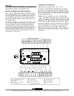
Page 2: ...install a jumper between the R and 24 terminals The 24 terminal must then be connected to the common side of the unit transformer Wiring The SZ1022 SZ1031 and SZ1035 use standard terminal designation...

Page 3: ...sensor only Using remote room sensor with both discharge and outdoor air sensors SZ1031 and SZ1035 only KEYPAD ACCESS The dipswitches in the thermostat cover shown above must be set in order to lock...

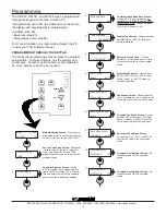
Page 4: ...aud Rate Screen If using a PC to do programming all controllers on a network must be set to the same baud rate Choose between 2 4K 4 8K 9 6K and 19 2K Display Type Screen Choose between FAHRENHEIT and...

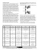
Page 5: ...4TH STAGE AS COOL 25 program setup ENABLE THIRD STAGE AS DISABLE 26 program setup HEAT STAGE 1 OFFSET 0F 27 program setup OCCUPIED COOL SETPOINT B 75F 16 program setup OCCUPIED COOL SETPOINT C 75F 17...

Page 6: ...etup ENABLE OUTDOOR AIR FUNCT YES 44 DISCHARGE AIR LOW LIMIT 45F ENABLE DISCHARGE AIR FUNCT YES program setup 41 program setup TIMECLOCK OUTPUT OCCUPIED CLOSED program setup 40 DISCHARGE AIR HIGH LIMI...

Page 7: ...CONDS DI3 USED FOR FILTER SERVICE program setup 50 program setup SET DI2 SETPOINT SHIFT 00F program setup 49 ENABLE SMART RECOVERY NO 52 program setup 51 program setup SET ACCESS CODE 248 55 MON 11 19...

Page 8: ...ed Times Screen Set hours and minutes of start and end times for up to two occupied periods Schedule Announcement Screen Announces the next screen Copy Schedule Screen Indicate whether or not to use t...

Page 9: ...such as with a switch or wind up timer If each occupancy period is about the same theaters meetings another option is to set the DI3 to external override and use the timed override button to put the...

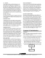
Page 10: ...ment to the building load The offset value is the amount away from the setpoint a stage will turn off By assign ing a stage a value other than zero you anticipate that the residual heat or cooling in...

Page 11: ...35 also have a P I option Without enabling this option stages turn on and off based on temperature vs setpoint alone as described above By enabling this option you allow a time factor to be added This...

Page 12: ...support you may be able to use the on board adjustment pots Refer to the Thermostat Sensor Calibration Tech Bulletin 1005 for details setpoint adjustment limits Change this to 20 F 11 1 C Press the P...

Page 13: ...the override is active and if so how many minutes remain ing service status MON 11 19 01 12 00 AM 72F service status SERVICE STATUS OK 1 service status OUTDOOR AIR TEMP 75F 3 service status DISCHARGE...

Page 14: ...allow the occupant to change the system mode is allowed by factory default To lock out access to system switching see programming step 5 SETTING CLOCK SCHEDULE The ability to set the clock and schedul...

Reviews: