


HR150, 200; ER150, 200 FRESH AIR VENTILATION SYSTEMS
11
68-0269
Airflow Balancing
Volume-balanced airflow in the ventilator is required. Volume
of outside air brought in must equal volume of air the unit
exhausts. If airflow is not correctly balanced:
• unit does not operate at its maximum efficiency.
• negative or positive air pressure can occur in the house.
• unit will not defrost properly.
• warranty can be voided.
Excessive positive pressure
can drive moist indoor air into
building external walls where it can condense (in cold
weather) and degrade structural components. Moist indoor air
can also cause keyholes to freeze.
Excessive negative pressure
can have several undesirable
side effects; in some geographic locations, soil gases such as
methane and radon can be drawn into the home through
basement/ground contact areas. Excessive negative pressure
can also cause back drafting of vented combustion equipment
when adequate combustion air supply is not provided.
Balancing Procedure
Six-inch (150 mm) diameter flow collars connected to inclined
or digital manometer, or magnehelic, with range of 0 to.25 in.
(0 to 62.5 Pa) of water are recommended for accurate airflow
measurements. To avoid airflow turbulence and incorrect
readings, flow stations should be located at a distant point of
at least five duct diameters; for example, 6 in. (150 mm) duct
requires five diameters x 6 in. (150 mm) = 30 in. (76 cm) from
nearest valve or flow restriction. This requirement applies to
both stale air to exchanger duct and fresh air to house duct.
Before balancing, make sure:
• all sealing of the ductwork system is completed.
• all of the ventilator system components are in place and
functioning properly.
• balancing dampers are fully open.
• unit is on High speed.
• airflows in branch lines to specific areas of house are
adjusted before balancing the unit. (A smoke pencil used at
the grilles is a good indicator of relative airflow for each
branch line.)
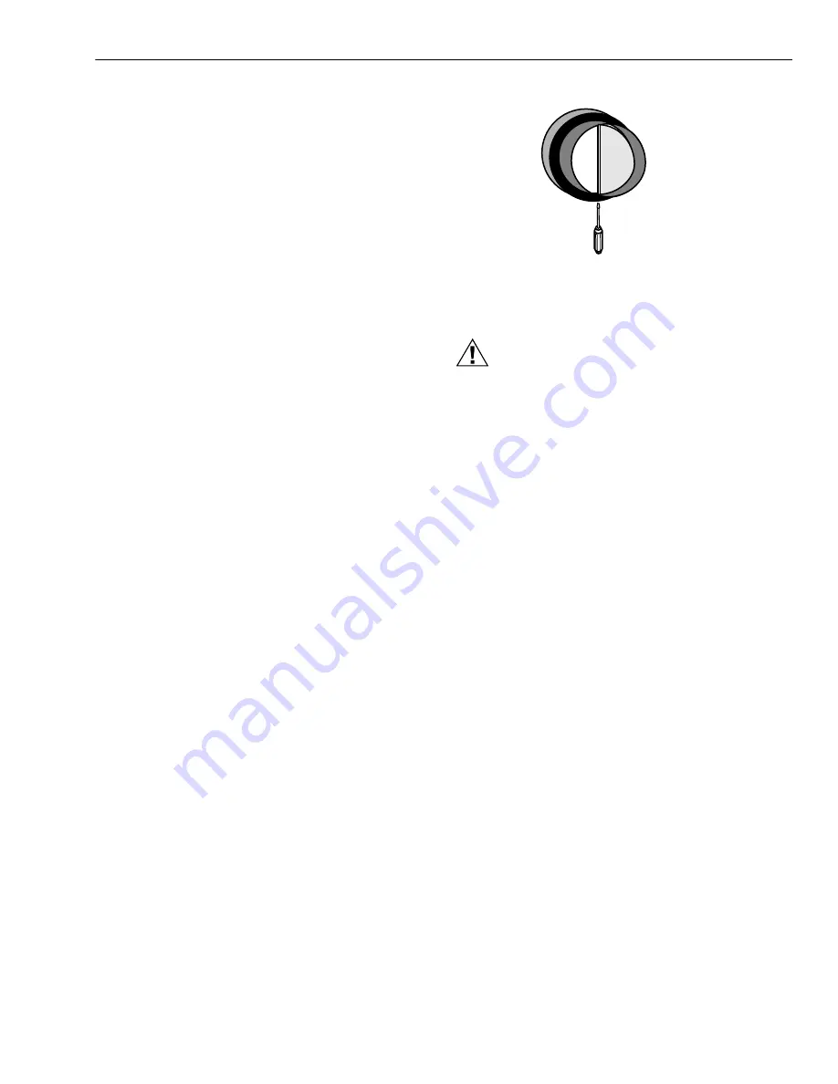
After taking readings in stale air and fresh air ducts, duct with
lower cfm (L/s) velocity reading should remain as is, while
duct with higher reading should be dampered back to match
lower reading. See Fig. 12.
Return unit to appropriate fan speed for normal operation.
STARTUP AND CHECKOUT
After installation is complete, check to be sure system is
working correctly. On units with microprocessor control, select
ventilation speed by touching fan control pad on base module
until desired speed is indicated. On units with manual control,
turn speed selection knob to desired speed. Activate two-wire
control devices in system to make sure devices switch
ventilator to High speed. For operating instructions, see
instructions packed with digital fan timer. Leave instructions
with homeowner.
Fig. 11. Balancing airflow.
SERVICE
CAUTION
Electrical Shock Hazard.
Can cause personal injury or equipment damage.
Disconnect power to unit before starting maintenance.
For maximum efficiency, the Fresh Air Ventilation System
must be maintained on a regular basis. Total Comfort System
recommends checking and cleaning at least twice a year,
preferably at the beginning of each heating and cooling
season.
Cleaning Filters and Core
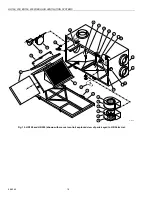
HR150 AND HR200 MODELS
Remove the room air filter, fresh air filter and heat transfer
core from the ventilator as a unit.
1.
Open ventilator door by loosening draw latches on top
of unit and swinging door open. For easier access,
remove door by moving it right to disengage hinges.
2.
Carefully grip ends of core, (be careful not to damage
aluminum fins); then pull evenly outward. Core fits
tightly, but slides out of channels.
3.
Once core is removed, filters can be removed by remov-
ing clips holding them in place. Note clip installation for
reassembly.
4.
Wash the filters and the core in warm soapy water. Do
not wash them in a dishwasher.
5.
Place the clean filter (wet or dry) over the core and
secure it in place with the clips.
6.
Reinstall core by sliding it into the four corner channels.
(Water cannot damage gasket and label on core ends,
so it is not necessary to remove them from the core.)
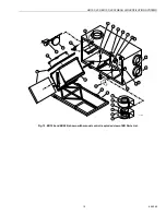
ER150 AND ER200 MODELS
1.
Open access door, carefully grip core ends and pull it
out evenly. Core fits tightly but slides out of cabinet.
2.
Remove filter clip, remove filters from core and rinse
filters with water or a combination of soap and water.
Do
not clean in a dishwasher.
3.
With filters removed, clean core with a vacuum cleaner.
Vacuum only filter sides of core to pull dirt back out of
core and not through it.
4.
Reinstall clean filter and reattach retaining clip.
5.
Reinstall clean core.
PUSH AND TURN WITH
SLOTTED SCREWDRIVER.
DAMPER AUTOMATICALLY
LOCKS WHEN PRESSURE
IS RELEASED.
M13462


