background image

HR150, 200; ER150, 200 FRESH AIR VENTILATION SYSTEMS

13

68-0269

TROUBLESHOOTING

See Table 1.

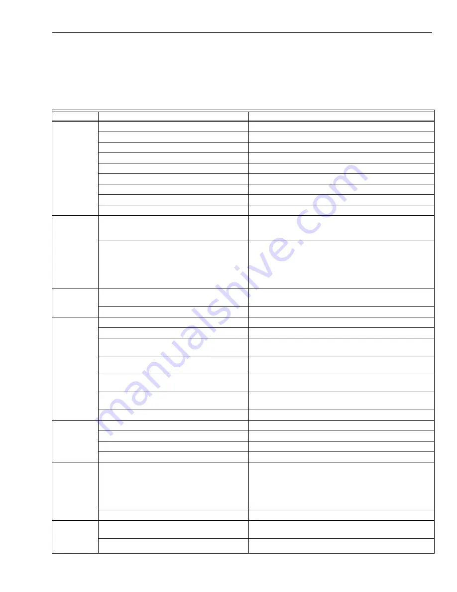
Table 1. Troubleshooting Guide.

Symptom

Cause

Solution

Poor 

airflow

Plugged outside hood 1/4 in. (6 mm) mesh.

• Clean exterior hoods or vents

Filters plugged.

• Remove and clean filter.

Core obstructed.

• Remove and clean core.

House grilles closed or blocked.

• Check and open grilles.

Dampers (if installed) are closed.

• Open and adjust dampers

Poor power supply at site.

• Have electrician check supply voltage at house.

• Ductwork is restricting airflow.

• Check duct installation.

Improper speed control setting.

• Increase speed of ventilator.

• Ventilator airflow improperly balanced.

• Have contractor balance ventilator airflow.

Supply air 

feels cold

• Poor location of supply grilles, airflow can irri-

tate the occupant.

• Locate grilles high on walls or under baseboards; install 

ceiling-mounted diffuser or grilles to avoid blowing directly 

on occupants (example: over a sofa).

• Outdoor temperature extremely cold.

• Turn down ventilator supply speed. Use a small duct heater 

(1kW to temper the supply air.

• Placement of furniture or closed doors is restricting move-

ment of air in the home.

• If supply air is ducted in furnace return, run furnace fan con-

tinuously to distribute ventilation air comfortably.

Dehumidistat 

is not oper-

ating

• Incorrect connection to external 24-volt control.

• Staple/nail is shorting out external low voltage.

• Check that correct wires were used.

• Check external wiring for a short.

• Check dehumidistat setting; it could be at Off. • Set dehumidistat at the desired setting.

Humidity      

levels are too 

high; conden-

sation appears 

on windows

• Dehumidistat is set too high.

• Set dehumidistat lower.

• Undersized ventilator (hot tub, indoor pool, etc) • Cover pools and hot tubs when not in use.
• Lifestyle of occupants.

• Avoid hanging clothes to dry, storing wood and venting 

clothes dryer inside. Consider moving wood outside.

• Moisture coming into home from crawl space 

not vented or heated.

• Vent crawl space and place vapor barrier on floor of crawl 

space.

• Moisture is remaining in bathroom and kitchen 

areas.

• Size bathroom ducts to remove moist air as effectively as 

possible; use bathroom fan to remove additional moisture.

• Condensation is forming in spring and fall.

• On humid days, as seasons change, condensation appears 

but air quality remains high with some ventilator use.

• Ventilator speed is set too low.

• Increase speed of ventilator.

Humidity lev-

els too low

• Dehumidistat control set too low.

• Set dehumidistat higher.

• Blower speed of ventilator is too high.

• Decrease ventilator blower speed.

• Lifestyle of occupants.

• Increase humidity with humidifiers.

• Ventilator airflow can be incorrectly balanced. • Have a contractor balance ventilator airflow.

Ventilator and/ 

or ducts have 

frost buildup

• Ventilator airflow is incorrectly balanced.

NOTE: Minimal frost build-up is expected on cores before 

unit initiates defrost cycle functions.

• Check operation of dampers in exhaust vent; damper vanes 

may be held open or damaged.

• Have HVAC contractor balance ventilator.

• Malfunction of ventilator defrost system.

• Have HVAC contractor check defrost system.

Condensation 

or ice buildup 

in insulated 

duct to outside

• Incomplete vapor barrier around insulated duct. • Tape and seal all joints.

• Tape any hole or tears made in outer duct covering.

• Hole or tear in outer duct covering.

• Ensure vapor barrier is completely sealed.

Summary of Contents for HR150

Page 1: ...verride Integral balancing dampers for quick installation Provides ventilation that helps contractors meet ASHRAE 62 89 4 speed fan control Automatic economical built in frost control for operation to...

Page 2: ...0 cfm aluminum core manual control and frost control HR200B 200 cfm aluminum cross flow core manual con trol and frost control ER150B 150 cfm moisture transferring core manual con trol and frost contr...

Page 3: ...ET SUPPLY AIR FLOW HR150 ER150 VENTILATION PERFORMANCE 0 GROSS SUPPLY GROSS EXHAUST 0 0 2 0 4 0 6 0 8 1 1 2 1 4 1 6 1 8 2 50 150 100 200 250 300 350 400 M6562A cfm L s n x 0 4719 in wg Pa n x 248 8 1...

Page 4: ...at is transferred from one airstream to the other as the air passes through the opposite sides of the heat transfer core See Fig 4 Fig 3 Duct connections and airflow 14 3 4 375 31 787 19 483 SERVICE C...

Page 5: ...ain line from the ventilator to a drain Use an existing electrical outlet with the appropriate current rating or install one close to the ventilator power cord Allow space for the drain line by placin...

Page 6: ...IALLY BASEMENTS FORCED AIR FURNACE COMBUSTION OR ELECTRIC M20854 RETURN AIR OUTDOORS NOTES 1 2 3 4 FURNACE BLOWER NEED NOT OPERATE TO PROVIDE GOOD AIR DISTRIBUTION QUALITY WITH THIS SYSTEM IF FURNACE...

Page 7: ...TO AND OUT OF THE HOUSE FRESH AIR SUPPLY HOOD STALE AIR EXHAUST HOOD FLEXIBLE INSULATED DUCTING WITH A VAPOR BARRIER VENTILATOR EXHAUSTS FROM KITCHEN AND OR BATHROOMS OR OTHER CENTRAL LOCATIONS TO OUT...

Page 8: ...1 Read these instructions carefully Failure to follow these instructions could damage the product or cause a haz ardous condition 2 Check the ratings on the product to make sure the prod uct is suita...

Page 9: ...confirm the proper polarity use a voltmeter or test lamp to make sure there is no power after the switch when the door is open Check between that point and ground on the cabinet This process must be...

Page 10: ...MOTOR DETAILS DEFROST DETAILS 205 ONLY DEFROST DETAILS 150 ONLY FAN MOTOR DIRECT MOUNTED CAPACITOR R E D W H I T E BLACK GREEN YELLOW ORANGE WHITE T9 T6 C A P PCB PLUG IN PLUG IN CONNECTOR RED RED ORA...

Page 11: ...KOUT After installation is complete check to be sure system is working correctly On units with microprocessor control select ventilation speed by touching fan control pad on base module until desired...

Page 12: ...e exhaust and fresh air supply hoods are not blocked or restricted by leaves grass or snow In winter be sure snow does not block hoods and frost does not accumulate on wire mesh bird screen IMPORTANT...

Page 13: ...conden sationappears on windows Dehumidistat is set too high Set dehumidistat lower Undersized ventilator hot tub indoor pool etc Cover pools and hot tubs when not in use Lifestyle of occupants Avoid...

Page 14: ...entilator drain lines Ensure O ring on drain nozzle adjusted correctly Look for kinks in line Ventilator is not level Level ventilator Drain lines are obstructed Check water drain connections Ventilat...

Page 15: ...r Foam Prefilter 11 Circuit Board for Damper Motor 12 208514 208514 Drain Spout 13 208515 208515 Drain T Fitting 14 208516 208516 Duct Collar Red 15 208517 208517 Duct Collar Blue 16 H Channel 24 3 4...

Page 16: ...wo 10 209722 209722 Clip for Foam Prefilter 12 208514 208514 Drain Spout 13 208515 208515 Drain T Fitting 14 208516 208516 Duct Collar Red 15 208517 208517 Duct Collar Blue 16 32002113 001 32002113 00...

Page 17: ...cting Elbow 4 in plastic 3 208373 Diffuser 4 in diameter 4 208374 Diffuser 5 in diameter 5 208375 Diffuser 6 in diameter 6 208379 Installation Parts Kit 7 272813 Flow Measuring Station 6 in 8 208372 A...

Page 18: ...FRESH AIR VENTILATION SYSTEMS 68 0269 18 Fig 12 HR150 and HR200 shown with manual control exploded view of parts keyed to HR Parts List 3 M15511B 1 2 4 5 6 7 25 8 8 12 13 14 15 23 22 24 21 28 16 17 1...

Page 19: ...R150 200 FRESH AIR VENTILATION SYSTEMS 19 68 0269 Fig 13 ER150 and ER200 shown with manual control exploded view of ER Parts List 3 M11889A 1 2 4 5 6 7 25 8 8 12 13 14 15 23 22 24 21 28 16 17 18 19 20...

Page 20: ...om yourhome Automation and Control Solutions Honeywell Honeywell Limited Honeywell Limit e 1985 Douglas Drive North 35 Dynamic Drive Golden Valley MN 55422 Scarborough Ontario M1V 4Z9 HR150 200 ER150...

Reviews: