


HR150, 200; ER150, 200 FRESH AIR VENTILATION SYSTEMS
68-0269
16
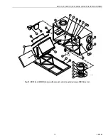
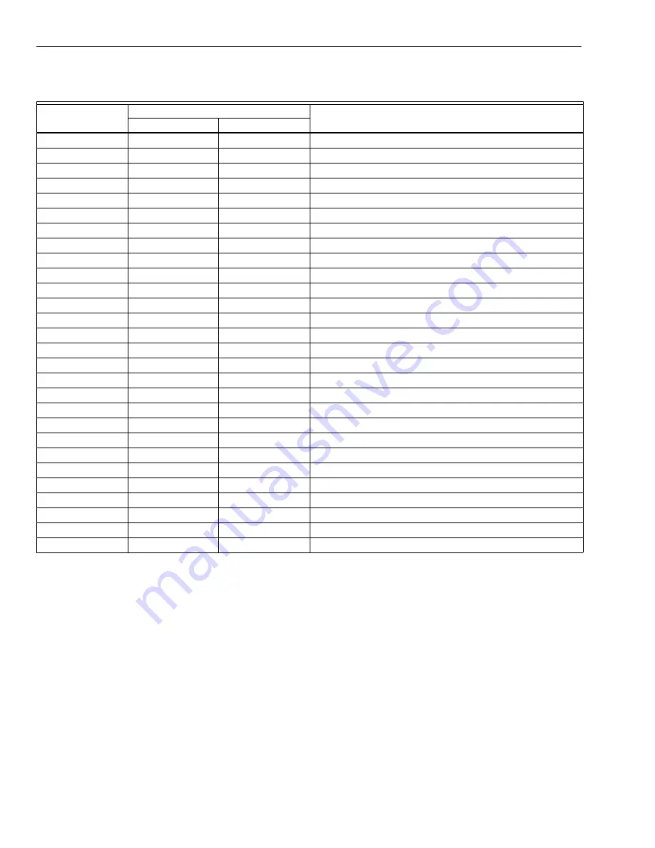
ER Parts List
Item Number
See Fig. 15
Part Number for
Description
ER150B
ER200B
1
32002074-001
32002074-001
Cross Flow Enthalpy Core
2
208359
208359
Blower Motor
3
208504
208508
Top Blower Wheel (Clockwise)
4
208505
208505
Top Blower Housing (Clockwise)
5
208506
208688
Bottom Blower Wheel (Counterclockwise)
6
208507
208507
Bottom Blower Housing (Counterclockwise)
7
209711
209711
Motor Capacitor
8
208509
208509
Condensate Pan, Left or Right
9
32002114-001
32002114-001
Foam Prefilter, Set of two
10
209722
209722
Clip for Foam Prefilter
12
208514
208514
Drain Spout
13
208515
208515
Drain “T” Fitting
14
208516
208516
Duct Collar, Red
15
208517
208517
Duct Collar, Blue
16
32002113-001
32002113-001
Guide Channel, Set of four
17
208519
208519
Door Hinge, Complete
18
208520
208520
Door Latch, Complete
19
209715
209715
Defrost Damper Motor, Power Return
20
208522
208522
Defrost Damper Door
21
209720
209720
Nylon Circuit Board Stand-Off
22
208526
208526
Speed Control Knob
23
208383
208383
Manual Speed Control, 5-Position
24
209719
209719
Manual Control Circuit Board
25
208365
208365
Thermistor Assembly
25
208381
208381
Temperature Sensor, Snap Disk
26
208368
208368
Door Interlock Switch
27
208366
208366
Door
28
209718
209718
Auto Transformer


