background image

HR150, 200; ER150, 200 FRESH AIR VENTILATION SYSTEMS

9

68-0269

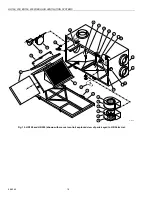
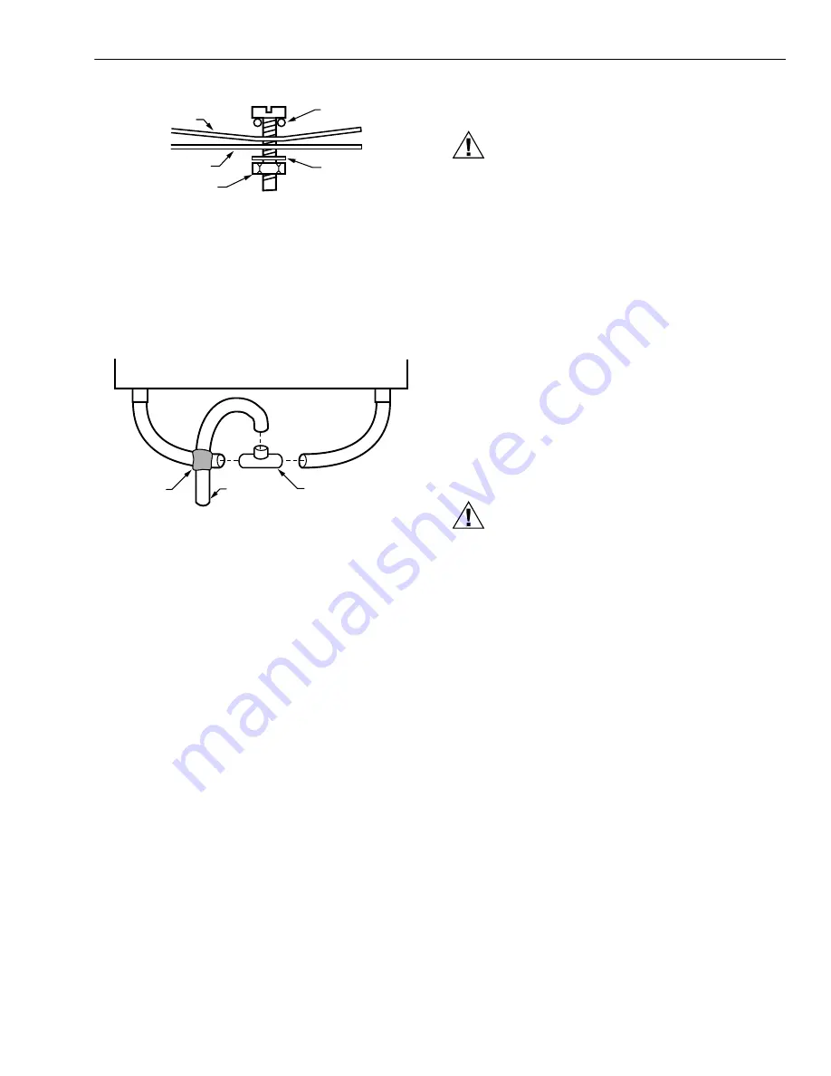
Fig. 8. Installing drain line.

Construct a P-trap using the plastic T-fitting provided. 

1.

Cut two lengths of 1/2 in. ID hose and connect each 

drain fitting to the end of the T-fitting. 
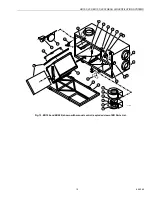
2.

Position the center leg of the T-fitting so it points 

upward. 

3.

Connect the drain line to the center leg and tape it in 

place to prevent any kinks. See Fig. 10.

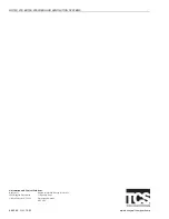
Fig. 9. Installing P-trap.

This creates a trap that will hold some condensation and 

prevent odors from being drawn up through the drain hose 

into the unit. If the unit is installed during a season when it is 

unlikely that condensation will form, fill the trap with tap water.

WIRING

CAUTION

Electrical Shock Hazard. 

Can cause personal injury.

Be sure the ventilator is properly grounded. To prevent 

electric shock when cleaning or servicing the unit, 

confirm the polarity of the power line that is switched 

by the safety (disconnect) switch.

The hot line (black) is the proper line to be switched. See 

Fig. 11. To confirm the proper polarity, use a voltmeter or test 

lamp to make sure there is no power after the switch when the 

door is open. Check between that point and ground (on the 

cabinet). This process must be done because occasionally 

some dwellings are improperly wired.

Heat Recovery Ventilator (HRV) and Energy 
Recovery Ventilator (ERV) Connections

The connector is a 3-prong, 120 Vac plug with ground. If 

further wiring is required, Honeywell recommends that a 

licensed electrician make all electrical connections. It is very 

important that the unit be properly grounded.

Digital Fan Timer Connections

CAUTION

Electrical Hazard.

Can cause equipment damage.

Disconnect HRV/ERV from power source before 

connecting or disconnecting digital fan timer or other 

device to HRV/ERV high-speed override terminals.

IMPORTANT

Do not connect external power sources to the high 

speed override terminals.

Mount the digital fan timer in a full or one-half depth electrical 

box in the living space. See Fig. 11 for the 20 minute timer and 

the 20/40/60 minute timer wiring diagrams. (See accessory 

parts list, items 9 through 11, for digital fan timer selection.)

M6552

DRAIN 
PAN

O RING

HR 
BOTTOM

WASHER

NUT

TO DRAIN

T FITTING

TAPE

M6551

Summary of Contents for HR150

Page 1: ...verride Integral balancing dampers for quick installation Provides ventilation that helps contractors meet ASHRAE 62 89 4 speed fan control Automatic economical built in frost control for operation to...

Page 2: ...0 cfm aluminum core manual control and frost control HR200B 200 cfm aluminum cross flow core manual con trol and frost control ER150B 150 cfm moisture transferring core manual con trol and frost contr...

Page 3: ...ET SUPPLY AIR FLOW HR150 ER150 VENTILATION PERFORMANCE 0 GROSS SUPPLY GROSS EXHAUST 0 0 2 0 4 0 6 0 8 1 1 2 1 4 1 6 1 8 2 50 150 100 200 250 300 350 400 M6562A cfm L s n x 0 4719 in wg Pa n x 248 8 1...

Page 4: ...at is transferred from one airstream to the other as the air passes through the opposite sides of the heat transfer core See Fig 4 Fig 3 Duct connections and airflow 14 3 4 375 31 787 19 483 SERVICE C...

Page 5: ...ain line from the ventilator to a drain Use an existing electrical outlet with the appropriate current rating or install one close to the ventilator power cord Allow space for the drain line by placin...

Page 6: ...IALLY BASEMENTS FORCED AIR FURNACE COMBUSTION OR ELECTRIC M20854 RETURN AIR OUTDOORS NOTES 1 2 3 4 FURNACE BLOWER NEED NOT OPERATE TO PROVIDE GOOD AIR DISTRIBUTION QUALITY WITH THIS SYSTEM IF FURNACE...

Page 7: ...TO AND OUT OF THE HOUSE FRESH AIR SUPPLY HOOD STALE AIR EXHAUST HOOD FLEXIBLE INSULATED DUCTING WITH A VAPOR BARRIER VENTILATOR EXHAUSTS FROM KITCHEN AND OR BATHROOMS OR OTHER CENTRAL LOCATIONS TO OUT...

Page 8: ...1 Read these instructions carefully Failure to follow these instructions could damage the product or cause a haz ardous condition 2 Check the ratings on the product to make sure the prod uct is suita...

Page 9: ...confirm the proper polarity use a voltmeter or test lamp to make sure there is no power after the switch when the door is open Check between that point and ground on the cabinet This process must be...

Page 10: ...MOTOR DETAILS DEFROST DETAILS 205 ONLY DEFROST DETAILS 150 ONLY FAN MOTOR DIRECT MOUNTED CAPACITOR R E D W H I T E BLACK GREEN YELLOW ORANGE WHITE T9 T6 C A P PCB PLUG IN PLUG IN CONNECTOR RED RED ORA...

Page 11: ...KOUT After installation is complete check to be sure system is working correctly On units with microprocessor control select ventilation speed by touching fan control pad on base module until desired...

Page 12: ...e exhaust and fresh air supply hoods are not blocked or restricted by leaves grass or snow In winter be sure snow does not block hoods and frost does not accumulate on wire mesh bird screen IMPORTANT...

Page 13: ...conden sationappears on windows Dehumidistat is set too high Set dehumidistat lower Undersized ventilator hot tub indoor pool etc Cover pools and hot tubs when not in use Lifestyle of occupants Avoid...

Page 14: ...entilator drain lines Ensure O ring on drain nozzle adjusted correctly Look for kinks in line Ventilator is not level Level ventilator Drain lines are obstructed Check water drain connections Ventilat...

Page 15: ...r Foam Prefilter 11 Circuit Board for Damper Motor 12 208514 208514 Drain Spout 13 208515 208515 Drain T Fitting 14 208516 208516 Duct Collar Red 15 208517 208517 Duct Collar Blue 16 H Channel 24 3 4...

Page 16: ...wo 10 209722 209722 Clip for Foam Prefilter 12 208514 208514 Drain Spout 13 208515 208515 Drain T Fitting 14 208516 208516 Duct Collar Red 15 208517 208517 Duct Collar Blue 16 32002113 001 32002113 00...

Page 17: ...cting Elbow 4 in plastic 3 208373 Diffuser 4 in diameter 4 208374 Diffuser 5 in diameter 5 208375 Diffuser 6 in diameter 6 208379 Installation Parts Kit 7 272813 Flow Measuring Station 6 in 8 208372 A...

Page 18: ...FRESH AIR VENTILATION SYSTEMS 68 0269 18 Fig 12 HR150 and HR200 shown with manual control exploded view of parts keyed to HR Parts List 3 M15511B 1 2 4 5 6 7 25 8 8 12 13 14 15 23 22 24 21 28 16 17 1...

Page 19: ...R150 200 FRESH AIR VENTILATION SYSTEMS 19 68 0269 Fig 13 ER150 and ER200 shown with manual control exploded view of ER Parts List 3 M11889A 1 2 4 5 6 7 25 8 8 12 13 14 15 23 22 24 21 28 16 17 18 19 20...

Page 20: ...om yourhome Automation and Control Solutions Honeywell Honeywell Limited Honeywell Limit e 1985 Douglas Drive North 35 Dynamic Drive Golden Valley MN 55422 Scarborough Ontario M1V 4Z9 HR150 200 ER150...

Reviews: