background image

 TCF EVO Line and TCF X Line 

Spare and wear parts


125 

14.9


Pneumatics  


Summary of Contents for TCF EVO Line

Page 1: ...e risk of injury anyone using installing repairing servicing or working near this appliance must read and under stand these instructions before performing any of the above tasks DO NOT DISPOSE HAND OVER TO THE USER Publication date 16 06 2021 Version 02 05 EN Valid from serial no P900129 ...

Page 2: ...he system Danger due to crushing This sign warns you that you can injure yourself by squeezing Operating instructions This symbol indicates that you must observe the operating instructions To the table of contents This symbol indicates that you can jump from any page of the operating instructions to the table of contents This helper gives you tips and helps you to carry out activities quickly and ...

Page 3: ...e state or setting etc is OFF INACTIVE or switched off Means that the state status is OK or on Means that the state status is not OK or off Load data Read in data Save data Message active Logout user Main page Message page Message active Message page no message active Feeder status active Feeder status inactive Settings Info page with backup and restore Language selection Break Stop ...

Page 4: ...f the screw units 24 7 0 Operation 25 7 1 Preparations before daily commissioning 25 8 0 Commissioning Decommissioning 27 8 1 Commissioning 27 8 2 Decommissioning 28 9 0 HMI Human Machine Interface 29 9 1 Basic structure 29 9 2 Login dialogue 29 9 2 1 User login 29 9 2 2 Password change 31 9 3 Messages 32 9 3 1 Overview of messages 32 9 3 2 Details messages 34 9 3 3 Filter messages 34 9 4 Main scr...

Page 5: ...dule 98 10 17 Module Remote Start TC HF V2 100 11 0 Connecting a USB stick to the display 101 12 0 Faults messages causes and remedies 103 12 1 Faults on the feeder 103 12 2 Messages 105 12 3 Settings TCF EVO Line 106 12 3 1 Set air volume and duration for the supply air blast 106 12 3 2 Set pause time 107 12 3 3 Set time for ticking off 107 12 3 4 Set time for SPiW 107 12 3 5 Remove jammed screws...

Page 6: ...X Line Table of Contents 6 14 9 Pneumatics 125 14 10 Sorting pot 126 14 11 Level control module 127 14 12 Vacuum module 129 14 13 Maintenance unit module 130 14 14 Module delivery unit 131 15 0 Storage 132 16 0 Disposal 132 ...

Page 7: ...TCF EVO Line and TCF X Line System overview 7 1 0 System overview 1 1 Assemblies TCFEVO Line Assembly Description 1 Housing 2 Base plate with valve battery 3 Sorting pot 4 Separation Abb 1 Assemblies ...

Page 8: ...ary or be on the left or right of the feeder 7 Control line or compressed air line Position can vary or be on the left or right of the feeder 8 Control line or compressed air line Position can vary or be on the left or right of the feeder 9 Feed hose 10 Maintenance unit Only with maintenance unit module 11 Mist lubricator Only for pneumatic screwdrivers 12 LED display blue Standby off 13 LED displ...

Page 9: ...TCF EVO Line and TCF X Line System overview 9 Abb 2 Structure of the system 4 15 17 16 10 11 ...

Page 10: ... to a tool There is a considerable risk of injury if the feed hose is not properly connected For the intended use observe the technical data see chapter3 0 page 13 The TCF EVO Line is to be used in closed rooms where the units cannot heat up above 45 C Unauthorised structural changes additions or conversions to the TCF EVO Line are prohibited and will void the warranty Intended use also includes o...

Page 11: ...with Annex VII Part B and we undertake to submit it to the market surveillance authorities via our documentation department on request Designation of the machine Feeding system Machine type TCF EVO Line and TCF X Line Year of manufacture 2021 The following EC Directives were applied Machinery Directive 2006 42 EC as amended on 17 05 2006 Directive 2014 42 EU on electromagnetic compatibility in the...

Page 12: ...bb 3 Open feed module The screws are transported upwards in the specified path of the sorting bowl 1 After they have passed the SPiW 2 they are aligned in the outlet 3 and fed to the separator 4 To prevent too many screws from piling up one after the other there is an inductive sensor in the cover of the outlet that switches the SPiW on when a certain quantity of screws is piled up In the separato...

Page 13: ...cover flap H3 640 Weight kg 39 Compressed air Supply according to ISO 8573 1 2010 7 4 4 Compressed air connection Air consumption approx L min 200 Nominal pressure or flow pressure bar 5 6 5 Max inlet pressure bar 10 Energy supply Mains connection V Hz 200 240 50200 240 60 Nominal power W 500 Hedging A 16 Noise emissionwith closed cover Feeding module dB A 60 dB A H2 H3 H B T ...

Page 14: ...TCF EVO Line must be kept clean and tidy Soiling and obstruction of the function of the system as well as restrictions in the freedom of movement of the operating personnel can lead to malfunctions and accidents 4 2 Personnel qualification 1 Personnel to be trained instructed or undergoing training may only work with the TCF EVO Line under the constant supervision of an experienced person 2 For wo...

Page 15: ... see chapter 9 6 2 Backup page This serves to be able to restore the system data in the event of an unintentional change a loss of the system data or a defect of the system computer 4 5 Passwords Various users are created on the TCF EVO Line by default These users have the default password 1234 In particular the administrator password should be changed Please be sure to change the passwords when c...

Page 16: ...2 Connect mains cable and compressed air supply of the feeder module 1 Connect the cable of the plug in power supply unit to the unit and plug the power supply unit into the mains socket 2 Connect the compressed air supply line according to ISO 8573 1 2010 7 4 4 hose Ø 8 mm customer supplied to the compressed air connection Abb 4 Compressed air connection Compressed air hose 90 ...

Page 17: ...se lines must be laid or secured in such a way that a hazard is avoided as far as possible 4 A hazard can occur for example if the hose or hose assembly is knocked around after being torn off e g due to external impact Hose line laid correctly Too narrow a radius ...

Page 18: ...ioning 18 6 0 Preparations before initial commissioning 1 Check the system for transport damage 2 Remove transport lock a Step 1 This is the delivery status of the TCF EVO Line or TCF X Line b Step 2 Take the transport lock in your hand as shown in the illustration ...

Page 19: ... X Line Preparations before initial commissioning 19 c Step 3 Remove the transport lock as shown in the illustration 3 Connect the hose assembly a Connect control line Connect the 5 pin plug to the electrical box see Fig 5 ...

Page 20: ...the downpipe plate see Fig6 Abb 6 Insert downpipe into downpipe plate Make sure that the downpipe is flush in the downpipe plate and fasten it with an Allen key see Fig7 Query sensors S1 and S2 for TC HS TC HF and TC AxFor TC HF 5 POLIG 4 POLIG OPTIONALExtern al OPTIONALHose sensor in front of the mouthpiece For the connection of the opposite side of the respective communication line please refer ...

Page 21: ...tic drive connect the air supply Connect the air supply as shown in Fig8 B Abb 8 Feed through feed hose A Air supply Pneumatic drive B 4 Connect optional communication lines When using the communication module the communication cable from the screwdriver control unit must be connected to the SUB D socket on the back see Fig 9 A B ...

Page 22: ... 10 RJ 45 only with modular bus system 5 If the maintenance unit module is present and a pneumatic screwdriver is available fill oil into the reservoir of the mist lubricator up to the maximum level mark in depressurised state Abb 11 Fill the oil into the mist lubricator 6 Type of oil Only use the type of oil recommended by the manufacturer of the screwdriver 7 Check all connections of the cables ...

Page 23: ...drop of oil should be visible on the mist lubricator The amount of oil can be changed through the adjusting screw see Fig12 Abb 12 Adjusting the mist lubricator clockwise to decrease the amount of oil counterclockwise to increase the amount of oil If the oil quantity is permanently too high faults can occur in the pneumatic drive If the oil quantity is permanently too low the service life of the p...

Page 24: ...e connected optional Fog lubricator filled only with pneumatic drive Connections power cable fixed Connections compressed air hose fixed Fog lubricator set only with pneumatic drive 6 1 Connection of the screw units Please refer to the respective operating instructions of the systems listed below to connect them to the TCF EVO Line or TCF XLine TC HS V2 or TC HF V2 handheld units TC AM TC AS or TC...

Page 25: ...ations before daily commissioning 1 Fill the fasteners into the sorting pot Fig13 Check that the sorting pot does not contain dirt or other foreign bodies Abb 13 Refill fasteners for screw lengths 20 mm fill 3 4 of the sorting bowl fill 1 2 of the sorting bowl for screw lengths 20 mm 3 4 1 2 20 mm 20 mm Connecting elements Filling i Filling i ...

Page 26: ...es or dirt getting into the sorting pot 3 Check the oil level in the mist lubricator If there is no oil in the reservoir it must be topped up For screwdrivers with electric drive no oil is needed in the mist lubricator Abb 14 Fill oil into the mist lubricator 4 Close the cover 1 Maximum Minimal Oil level ...

Page 27: ...essed air to approx 5 6 5 bar flow pressure at the adjusting wheel of the maintenance unit of your supply air for the TCF EVO Line If the module maintenance unit is not present please ensure a constant compressed air supply of approx 5 6 5 bar flow pressure Commissioning checklist TCF EVO Line switched on Compressed air set to 5 6 5 bar flow pressure Feed hose sits firmly on the TCF EVO Line Screw...

Page 28: ...sioning 1 Press the red button on the display and pull out the unit plug The system is disconnected from the voltage 2 Close the shut off valve of the compressed air supply Decommissioning checklist TCF EVO Line switched off Pull out the appliance plug Stopcock closed Press ...

Page 29: ...2 Login dialogue 9 2 1 User login Increased user rights are required for certain functions or menu items E g to change settings an administrator must be logged in If a higher user group is required the login dialogue is displayed In this dialogue a user can be selected and the password entered After successful login the desired function must be clicked again to open or execute it The login dialogu...

Page 30: ...F EVO Line and TCF X Line Human Machine Interface 30 Element Description Ok Confirmation of the user password entry Cancel Canceling the user login Change Password Call dialogue for changing the password ...

Page 31: ...TCF EVO Line and TCF X Line Human Machine Interface 31 9 2 2 Password change Dialogue for changing the password Element Description OK Confirmation of the password entry Cancel Cancel Change Password ...

Page 32: ...ia the flashing LED of the screen is displayed Furthermore the main menu item for the message page is coloured red Element Description State Status of the message Cancel Time of occurrence of the message Text Detailed description of the message Button to confirm a selected marked message Necessary when the operator needs to check something E g the Message Please check if screw is jammed Wait Blade...

Page 33: ...he Message Please check if screw is jammed Wait Blade reaches working position After the automatic fault clearance was not successful Button for the TCS service technician to delete all messages from the message list Button to display the details of a selected marked message Calling up the dialogue for filtering the message entries Example of a confirmed message ...

Page 34: ... in full in the tabular view Example of a detail message page 9 3 3 Filter messages With the Filter dialogue messages with certain statuses can be hidden or shown in the message table 9 4 Main screen The main screen is accessible via the Main Menu with this symbol to reach The main page has the submenus by default Overview Manual If the module Count screws is activated the submenu is also activate...

Page 35: ... X Line Human Machine Interface 35 9 4 1 Overview The main page is displayed as soon as the unit has been started after power has been supplied Main page without pressure switch module Main page with pressure switch module ...

Page 36: ...with the communication module active The screwing results are displayed accordingly Here is an example of an IO screw connection with a green background Main page with the communication module active Here is an example of an NIO screw connection with a red background ...

Page 37: ...the main page is also coloured accordingly Background green Screws IO Background red Screws NIO Compressed air ok Button to display the details of a selected marked message Act Shot time Display of the current firing time This function is active with the hose sensor module Otherwise no value is output here Total screws Total number of screws that have been separated so far Display of the selected ...

Page 38: ... of maintenance or errors Element Description Reverse valve Injection Switching the supplementary air on off Reverse valve Blade AST Move the blade of the screwdriver to AST or GST Reversing the valve Singling out Move the cylinder to AST or GST to separate a screw Reroute vacuum Switch the vacuum on off on the screwdriver With display of the vacuum value This function is only available with modul...

Page 39: ...ement Description Target quantity Field for entering the target quantity to be portioned The value can be preset via the settings but can also be changed manually Actual quantity Field for displaying the current quantity that has already been portioned Reversing the valve Singling out Cylinder for separating a screw on AST or GST drive Reroute vacuum Switch the vacuum on off on the screwdriver Wit...

Page 40: ...rt For this purpose the module Screw counting ext start can be activated Or the control can be carried out via the Bus system module Pause button button to interrupt portioning After restarting portioning continues at the current actual quantity Actual quantity is not set to 0 Stop button button to cancel portioning After a restart it is started at the actual quantity of 0 9 4 4 Standby The standb...

Page 41: ...d Display of the current firing time This function is active with the module hose sensor system Otherwise no value is output here Chopping time Duration for separating a screw This function is only active with the separation sensor module Duration of the separation process extend cylinder separate screw return cylinder to GST Time between re positions Start Duration between 2 separation processes ...

Page 42: ...page allows you to save the settings and licence data of the feeder to an external USB We strongly recommend creating a complete backup before making any changes to settings etc so that the old status can be restored without much effort Furthermore regular data backups should be made and a data backup after commissioning A USB data storage device is required for the backup This can be connected to...

Page 43: ...ating a backup of the settings Backup All Creating a backup of the settings and licence file If the backup cannot be executed a message is displayed For example if no USB is connected during the backup the following message appears The settings and licence data are stored on the USB data carrier in files preceded by a time stamp Here is an example ...

Page 44: ...us before importing the old data First insert the USB memory chapter 11 0 Connecting the USB stick to the display and then open the Restore page so that the files of the USB can be listed If necessary insert the USB with backup files close the Restore page and open it again On the restore page a list of possible restore files is displayed To select a file click on it so that it is explicitly displ...

Page 45: ... Line and TCF X Line Human Machine Interface 45 Depending on the selected file the settings or parameters can then be restored via the Restore settings button or the licence data via the Restore licence button ...

Page 46: ...TCF EVO Line and TCF X Line Human Machine Interface 46 9 7 Settings page Has 6 submenus General User Logging Input Output Self Test ...

Page 47: ...e submenu items Pot o General o Vibration o Trapdoor o Sorting air Chopper o Chopper o Shoot Screwdriver o TC HS o TC HF Modules o Depth shut off o Sensors o Level o Pressure switch o Portioner Licences o Function modules o Sensor modules o Communication modules o Depth shut off o Other modules o Serial number ...

Page 48: ...The General settings page offers various basic settings for the display Element Description Switch standby Switching the Feeder to Standby Set time Dialogue for setting the time Set time zone Dialogue for setting the time zone Set IP Change the IP address of the display ...

Page 49: ...TCF EVO Line and TCF X Line Human Machine Interface 49 Background lighting Adjusting the backlight German Switching the display language to German English Switching the display language to English ...

Page 50: ...tatus indicator Signal input is inactive In this example it means that sensor S1 is not switched i e it is off Green status indicator Signal input is active In this example it means that the sensor S2 is switched on Analogue values The analogue measured values e g of vacuum and pressure are also displayed as raw values These are not converted into their corresponding units of measurement The conve...

Page 51: ...updated as frequently quickly as the signal run is processed at the control computer Element Description Blue status indicator Signal output is inactive In this example it means that the valve for vacuum on is switched off Green status indicator Signal output is active In this example it means that the valve for Lock trapdoor is active Analogue values The analogue output values are also displayed ...

Page 52: ...sensor is free sec Defines the time when the pot should start pumping screws again If the sensor does not detect a screw for the specified time before the chopper and no other condition prevents this the pot is switched on Promote follow up time if sensor occupied sec Duration of how long the drip continues to feed screws once a screw has been detected by the sensor before the chopper If the signa...

Page 53: ...sage is displayed This time is particularly relevant if no level sensor is installed All parameters not only those of the current display can be read in again by pressing the Read button If changes were made by mistake and not yet saved the saved values can be read in again All parameters not only those of the current display can be saved by the Save button so that the change is still available an...

Page 54: ...eed percent Conveying speed of the screws in the pot A value between 0 100 can be set Where 100 is the maximum speed All parameters not only those of the current display can be read in again by pressing the Read button If changes were made by mistake and not yet saved the saved values can be read in again All parameters not only those of the current display can be saved by the Save button so that ...

Page 55: ...me defined here Down if sensor occupied for High when sensor free for sec The trap door is closed so that screws are conveyed back to the chopper if the sensor in front of the chopper is permanently unoccupied for the time defined here All parameters not only those of the current display can be read in again by pressing the Read button If changes were made by mistake and not yet saved the saved va...

Page 56: ...witched on Sorting air off sec Specifies the time for which the sorting air is to be switched off in the case of pulsating sorting air If the value is set to 0 the sorting air is switched on permanently when the feeder is active All parameters not only those of the current display can be read in again by pressing the Read button If changes were made by mistake and not yet saved the saved values ca...

Page 57: ...the time for which the chopper is controlled on AST in order to separate a screw This time is especially important if the module separation sensor is not active If the separation sensor module is active the time is also used to delay the retraction of the cylinder for the specified time after the end position sensor has been reached Activate cylinder on GST for sec Specifies the time for which the...

Page 58: ...rent display can be read in again by pressing the Read button If changes were made by mistake and not yet saved the saved values can be read in again All parameters not only those of the current display can be saved by the Save button so that the change is still available and used after a restart ...

Page 59: ...lementary air may be switched on After this time the air is switched off value is particularly relevant for the hose sensor system module Reshoot time sec Defines the time in which the air blast is still maintained after the delivery time has expired or the screw on the 2nd hose sensor has been detected value is particularly relevant for the hose sensor system module Monitoring hose sensor S2 inac...

Page 60: ...rent display can be read in again by pressing the Read button If changes were made by mistake and not yet saved the saved values can be read in again All parameters not only those of the current display can be saved by the Save button so that the change is still available and used after a restart ...

Page 61: ... current configuration via the buttons displayed above Adjustment of this data should only be carried out by trained personnel Incorrect configurations can lead to malfunctions of the feeder Before making changes it is always advisable to make a backup of the current settings See also 9 6 2 Backup page 9 6 3 Restore page 9 10 1 General The licence menu has the following submenus for the various fu...

Page 62: ...a the keyboard is possible but not recommended Element Description Module name e g module Schaurber TC HF V2 Name of the module Activation state module Activation state of a module Module active Module inactive License code input field Field with the representation of the licence code Attention only a part of the licence code is displayed Status licence check Display whether the entered licence wa...

Page 63: ...current display can be re read by pressing the Read button If changes were made by mistake and not yet saved the saved values can be read in again All licence data not only that of the current display can be saved by the Save button so that the change is still available and used after a restart ...

Page 64: ... any time The licence file can be requested from TCS To create the licence file the serial number of the unit from the type plate is required see Fig 2 and also the software serial number of the unit You can read this out as follows Settings administrator required Main menu Licences Submenu Serial No ...

Page 65: ...TCF EVO Line and TCF X Line Human Machine Interface 65 For the activation of modules you will receive a licence file that you can import into the feeder ...

Page 66: ...e 1 Connect the USB stick preferably empty and checked by a virus scanner to a PC and copy the licence file name freely selectable Usually lic xml or lic2import xml or 20210210_lic xml into the root folder 2 Connect the USB stick preferably empty and checked by a virus scanner to a PC and copy the licence file name freely selectable Usually lic xml or lic2import xml or 20210210_lic xml into the ro...

Page 67: ...man Machine Interface 67 3 Change display to Settings administrator required Main menu Licences 4 Start importing the new licence file by pressing the Import button 5 If the USB stick is not recognised an error message is displayed ...

Page 68: ...o that the name appears in the upper field 7 Press the Restore licence button to import the licence data If licence data already exists a backup of the existing licence file is created on the USB beforehand A message with the result is displayed If there was no lic xml on the device yet the message that no backup could be made for the old file is also displayed ...

Page 69: ...witch back to the licence settings Settings Administrator required Main menu Licences The licence codes are displayed By clicking on the on off button you can activate or deactivate licences After the licence code it is displayed whether the licence code has been accepted ...

Page 70: ...n Machine Interface 70 9 After checking the licences the new licence data must still be saved To do this the save button must be pressed If the licence data is not saved the old data can be displayed again by pressing the read button ...

Page 71: ...and TCF X Line Human Machine Interface 71 9 10 4 Serial number The serial number of the feeder is displayed on the serial no page This is important among other things for the request for licences or support requests ...

Page 72: ...if the corresponding modules are enabled and active Adjustment of this data should only be carried out by trained specialist personnel Incorrect configurations can lead to malfunctions of the feeder Before making changes it is always advisable to make a backup of the current settings See also 9 6 2 Backup page 9 6 3 Restore page 10 1Maintenance unit module Filter regulator with pressure gauge Oile...

Page 73: ...e settings of the TC HS screwdriver could be made here Element Description All parameters not only those of the current display can be read in again by pressing the Read button If changes were made by mistake and not yet saved the saved values can be read in again All parameters not only those of the current display can be saved by the Save button so that the change is still available and used aft...

Page 74: ... with blade centre position active If the option is set to ACTIVE the blade is moved to the middle position after separating a screw Reload with blade Extended active If the option is set to ACTIVE the blade is fully extended after separating a screw Blade fully extended AST Delay sec If this value is greater than 0 and the option Reload with blade extended active is active the blade extension is ...

Page 75: ...lable and used after a restart 10 4Module TC HF V2 Lever start Instead of the standard handle the trigger mechanism is converted to lever start 10 5Module TC Ax Control of the automatic add on units TC AM TC AS TC AH and TC HF Hybrid Digital interface for controlling the TC automatic and hybrid units Complete control incl feedback via sensor valves already installed in the TCF EVO LINE For example...

Page 76: ... sensors Element Description Screw not recognised Interference suppression after sec Defines the max time until the screw on the hose sensor S1 must be detected If the screw is not detected within this time the fault clearance is triggered unless the maximum number of fault clearances has been reached Screw not recognised max interference suppression one after the other Number of max permitted int...

Page 77: ...e read in again by pressing the Read button If changes were made by mistake and not yet saved the saved values can be read in again All parameters not only those of the current display can be saved by the Save button so that the change is still available and used after a restart 10 7Bus system module ModBus TCP only in combination with module TC Ax Control of the entire TCF EVO Line as well as ext...

Page 78: ...carried out Q06 ZuschiessenLaeuft 6 1 Signal that the grant process is underway Q07 ZuschiessenIO 7 1 Signal that the shooting has been successfully completed Q08 GrantNIO 8 1 Signal that the shooting has not been completed successfully Q09 BladeAtFrontAST 9 1 Signal whether the blade is in the working position extended Q10 BladeIstHinGST 10 1 Signal whether the blade is in the home position retra...

Page 79: ...her the connection is active Holding Register Size 5 Designation Address Start Data Size Description QA01 DruckAktDeziBar 61 1 Integer Value of the current pressure in Dezi Bar i e PressureActDeziBar 10 Current pressure in bar QA02 Vacuum DeziBar 62 1 Integer value of the vacuum value in Dezi Bar i e VacuumDeziBar 10 vacuum value in bar QA03 Displacement measurementScrewdriverTCHFEvoDeziMM 63 1 In...

Page 80: ...e set to SeparateFinished OFF SeparateIO OFF SeparateNIO OFF and the singling process started As soon as the separation process is active the feeder output signal SeparateRunning is set to ON If the screw has been separated and if necessary detected by the hose sensor S1 if the hose sensor module is active the feeder output signal SeparateIO ON set and as soon as the process is completely finished...

Page 81: ...lank of ZuschiessenStart The feeder outputs are set to Feed ready OFF ZuschiessenIO OFF AllowNIO OFF set and the grant process started As soon as the feeding process is active the feeder output signal Feeding running is set to ON If the screw has been closed and if necessary detected by the hose sensor S2 if the hose sensor module is active the feeder output signal ZuschiessenIO ON set and as soon...

Page 82: ... VacuumA 36 1 Switch on vacuum request at the screwdriver TC HF I07 ModScrewsCntStart 37 1 Request to start separating and counting screws counter value is zeroed I08 ModScrewsCntPause 38 1 Requirement to pause the separation and counting of screws counter value is not zeroed I09 ModScrewsCntStop 39 1 Requirement to stop the separation and counting of screws I10 MsgQuittAllError 40 1 Request ackno...

Page 83: ...s the feeder can be terminated from standby via Modbus I15 StandbyOff 45 1 Cancel standby of the feeder Attention only functional from V1 7 Holding Register Size 1 Designation Address Start Data Size Description IA01 ModScrewsCntTargetQuantityPc 71 1 UInt Value of the number of screws to be separated ...

Page 84: ... necessary request standby off via StandbyOff_I15 and check the signal again Request Standby off must be reset Check FaultActive Q18 OFF Check whether a fault is active If a fault is active it can be acknowledged e g via MsgQuittAllError I10 ON request acknowledgement and check the signal again Request for acknowledgement must be reset The error numbers are transmitted in the Error No field QA05 S...

Page 85: ...running is set And the signals Done IO and NIO are reset Wait SeparateRunning Q02 ON Wait until the singling process is reported Set SeparateStart I01 OFF Take back the starting signal for the singling process Separation successful Set SeparateIO Q03 ON Set SeparateNIO Q04 OFF Separation unsuccessful after no of retries Set SeparateIO Q03 OFF Set SeparateNIO Q04 ON Separation result is set when th...

Page 86: ...rted completed Sets SeparateFinished Q01 ON As soon as the separation process is finished the KZ SeparationComplete is set Sets SeparateRunning Q02 OFF As soon as the singling process is finished the KZ SinglingRunning is switched off again Evaluation SeparateIO Q03 SeparateNIO Q04 Evaluation of the singling result SeparateIO Q03 ON if process has been completed successfully SeparateNIO Q04 ON if ...

Page 87: ...gain Request Standby off must be reset Check FaultActive Q18 OFF Check whether a fault is active If a fault is active it can be acknowledged e g via MsgQuittAllError I10 ON request acknowledgement and check the signal again Request for acknowledgement must be reset The error numbers are transmitted in the Error No field QA05 See also chapter 9 Messages Set Start shooting I02 OFF Set the signal Fee...

Page 88: ...e position I13 Sets GrantOn Q10 ON Grant air is activated Wait for Infeed running Q06 ON Wait until grant process is reported Set Start shooting I02 OFF Take back start signal for grant process Grant successful Set ZuschiessenIO Q07 ON Set AllowNIO Q08 OFF Separation unsuccessful after no of retries Set ZuschiessenIO Q07 OFF Set AllowNIO Q08 ON Grant result is set when process is close to completi...

Page 89: ...he grant process is completed the GrantComplete flag is set Sets Feed Runs Q06 OFF As soon as the granting process is finished the granting process KZ is switched off again Evaluation ZuschiessenIO Q07 ZuschiessenNIO Q08 Evaluation of the grant result ZuschiessenIO Q07 ON when process has been successfully completed AddNIO Q08 ON if the process is not successful even after the configured retries ...

Page 90: ...os edge 1 sec present signal I09 ModScrewCntStop Stop the execution of the screw count immediately Pos edge I08 ModScrewCntPause End execution after completion of the current separation Neg Edge I08 ModScrewCntPause If no stop of the screw counting I09 ModScrewsCntStop has been requested in the meantime the separation is continued again from the current number of pieces Start of the separation Sta...

Page 91: ...wCntStart to off for min one communication cycle so that the feeder PLC can detect the signal change that screw counting is switched off Check ModScrewsCntRunning Q15 OFF Do not start a new screw counting process until no process is running Therefore check the ModScrewsCntLauft signal for off Set ModScrewCntStart I07 ON As soon as the predecessor conditions are fulfilled a new screw counting proce...

Page 92: ...e This interrupts the separation process In the case of a pause any separation of a screw that has already been started is first completely executed before the sequence is paused Sets ModScrewsCntRunnin g Q15 OFF As soon as the current active separation is completed the separation process is ended and the Running signal is reset Set ModScrewsCntPause I08 OFF If the ModScrewsCntPaus e signal is wit...

Page 93: ...TCF EVO Line and TCF X Line Functions of the modules and settings 93 Set ModScrewsCntStop I09 OFF Cancel stop signal again ...

Page 94: ...cuum module Vacuum screw joint for complicated and deep screw joints High end vacuum generator and sensor technology installed in the TCF EVO Line 10 10 Depth cut off for pneumatic and electric drives Screw depth steplessly adjustable by sensor An overrun time can be defined for the depth connection module Element Description Follow up time sec Defines the run on time after reaching sensor S2 befo...

Page 95: ...by pressing the Read button If changes were made by mistake and not yet saved the saved values can be read in again All parameters not only those of the current display can be saved by the Save button so that the change is still available and used after a restart 10 11 Module feed unit for TC Ax Feed stroke 30 100 mm for stationary units TC AX ...

Page 96: ...ate or on the carriage with feed stroke for TX Ax units 10 13 Screw Counting Portioning Module Counting function for screws end hose This module turns TCF EVO Line into a screw portioner Screws are dispensed piece by piece Output speed up to 0 5 seconds per screw possible For the portioner module the quantity to be portioned by default can be defined ...

Page 97: ...hanges were made by mistake and not yet saved the saved values can be read in again All parameters not only those of the current display can be saved by the Save button so that the change is still available and used after a restart 10 14 Pressure switch module Optional pressure sensor The standard pressure switch is replaced by a pressure sensor The current pressure is shown on the display Further...

Page 98: ...e All parameters not only those of the current display can be read in again by pressing the Read button If changes were made by mistake and not yet saved the saved values can be read in again All parameters not only those of the current display can be saved by the Save button so that the change is still available and used after a restart 10 15 Module external start For Screw Counting Portioning Mo...

Page 99: ...off by this Cancel fault after sec If the level sensor continuously reports for the time specified here that there are screws in the pot i e that it is not empty the pot empty message is cancelled All parameters not only those of the current display can be read in again by pressing the Read button If changes were made by mistake and not yet saved the saved values can be read in again All parameter...

Page 100: ...TCF EVO Line and TCF X Line Functions of the modules and settings 100 10 17 Module Remote Start TC HF V2 Remote start for TC HF V2 Enables remote start of the TC HF V2 e g for an external start handle ...

Page 101: ...for the backup or restore of settings Please always use only a checked data medium that has been checked by a virus scanner To connect the USB storage device to the display we recommend putting the feeder in standby mode Open the bonnet completely so that accidental folding down is avoided The USB connection on the display is located in the feeder housing on the left narrow side of the display Ple...

Page 102: ...TCF EVO Line and TCF X Line Connection of USB stick to the display 102 ...

Page 103: ...Observe the correct screw type No foreign bodies or dirt may get into the sorting bowl Chapter 7 1 Feed hose blocked Loosen the feed hose and remove objects in the feed hose Take care when handling compressed air Risk of injury from objects shooting out Replace feed hose Chapter 13 1 Feed hose strong kinked Observe the minimum bending radius 150 mm of the cable conduit package Pressure for the sup...

Page 104: ...let rails Remove jammed screws Chapter 12 3 5 Screws jam on the singling Loosen jammed screws Chapter 12 3 6 Dirt or foreign objects in the sorting pot Switch off system Empty and clean sorting bowl Screws dance and fall back into the pot at the outlet end Reduce conveying speed Chapter 12 3 7 If you are unable to eliminate the malfunctions with this information our customer service will be happy ...

Page 105: ...is only permitted with separation chopper in GST Wait for GST of the separating cylinder chopper 1004 Screw not closed Please check and confirm 1005 Please check whether the screw is jammed Wait Blade reaches working position 1006 Please check whether the screw is jammed Wait Blade reaches home position 1007 Please fill the pot Level has not been reached 1008 Pressure below 5 bar flow pressure Sys...

Page 106: ... screw larger volume The supply air shock is set correctly when the screws reach the mouthpiece without interference but are not shot out of the mouthpiece To set the duration of the supply air blast please follow the instructions in chapter 9 9 2 Supply air blast To adjust the air volume of the supply air blast turn the throttle screw see Fig15 clockwise to reduce the air volume counterclockwise ...

Page 107: ...s pulled back the screw can fall through the singling and thus can no longer be clamped The maximum time should be set so that the separating cylinder does not remain extended for an unnecessarily long time after the screw has fallen through 12 3 4 Set time for SPiW To set the time for the SPiW congestion free buffer section through intelligent helix management proceed as described in chapter 9 8 ...

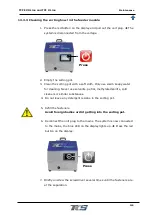
Page 108: ... the display and pull out the unit plug The system is disconnected from the voltage 2 Close the shut off valve of the compressed air supply 3 Loosen the 2 fastening screws of the baffle A in Fig16 Pay attention to the sensor B in Fig16 and the air supply for the sorting air C in Fig16 Abb 16 Outlet rail 4 Remove the jammed screws A Press B C ...

Page 109: ...e Faults messages causes and remedies 109 5 Put the chicane back on 6 Reconnect the unit plug to the mains The system is now connected to the mains the blue LED on the display lights up Press the red button on the display Press ...

Page 110: ...gling unit 1 Press the red button on the display and pull out the unit plug The system is disconnected from the voltage 2 Disconnect the compressed air supply from the TCF EVO Line 3 Lift the cover plate of the separator A in Fig17 and turn the cover plate to the side B in Fig17 Abb 17 Separation A Press B ...

Page 111: ... over the singling 6 Reconnect compressed air 7 Reconnect the unit plug to the mains The system is now connected to the mains the blue LED on the display lights up Press the red button on the display 12 3 7 Set the conveying speed of the sorting bowl To set the conveyor speed proceed as described in chapter 9 8 2 Vibration ...

Page 112: ...ect the mains plug before starting work Danger due to electric shock Safety instructions for dealing with the electrics Work on all parts of the system that are supplied with electrical energy may only be carried out by qualified electricians The operating voltage required for the system can have fatal consequences if live parts are touched Therefore switch off the TCF EVO Line and disconnect the ...

Page 113: ...e sorting bowl Chapter 13 3 3 Dosage of the mist lubricator Chapter 7 1 Chapter 6 0 Compressed air supply Drain condensation water only if no automatic water separation is available Check the connections of the pneumatic hoses Chapter 13 3 2 Fill up the mist lubricator Only for screwdrivers with pneumatic drive Chapter 7 0 All maintenance work must be carried out after 1000 hours of use at the lat...

Page 114: ...for integrity Leaky pneumatic hoses can be detected acoustically by the compressed air whistling off Check the pneumatic hoses for tight fit If loose pneumatic hoses come loose they can whirl around uncontrollably and painfully hit parts of the body If work on the pneumatics inside the feeder module is necessary have it done by Technik Center Schraubsysteme GmbH Because if connections to the pneum...

Page 115: ... soapy water for cleaning Never use solvents petrol methylated spirits cold cleaners or similar substances 4 Do not leave any detergent residue in the sorting pot 5 Refill the fasteners Avoid foreign bodies or dirt getting into the sorting pot 6 Reconnect the unit plug to the mains The system is now connected to the mains the blue LED on the display lights up Press the red button on the display 7 ...

Page 116: ...nately unable to state quantities 14 2Wear parts For the wearing parts V marked in the parts list we recommend stocking them according to the degree of use in order to reduce machine downtimes to a minimum 14 3Spare parts For the spare parts marked in the parts lists E we recommend stocking minimum quantities for units with high availability requirements 14 4Reading the parts lists On the followin...

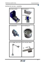
Page 117: ...Line and TCF X Line Spare and wear parts 117 14 5Parts list overview assemblies 14 6 Feed module 14 7 Guide rail 14 8 Separation 14 9 Pneumatics 14 10 Sorting pot 14 11 Module level control 14 12 Vacuum module ...

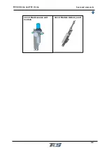
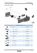
Page 118: ...TCF EVO Line and TCF X Line Spare and wear parts 118 14 13 Maintenance unit module 14 14 Module delivery unit ...

Page 119: ...TCF EVO Line and TCF X Line Spare and wear parts 119 14 6Feeding module ...

Page 120: ...TCF EVO Line and TCF X Line Spare and wear parts 120 14 7Guide rail ...

Page 121: ... 1000005079 V 5 Guide rail cover 1 1000005080 V 6 Guide rail Sensor plate 1 1000005081 E 7 Sensor 1 2000001390 V 8 Guide rail Blower nozzle 1 1000005082 E 9 Pneumatic connection straight 1 2000002138 E 10 Angle plate 1 1000003650 V 11 Guide plate 1 1000003649 V 12 Nut M4 2 Nut M4 E 13 Screw M5x12 2 Screw M5x12 E 14 Screw M4x25 2 Screw M4x25 E 15 Screw M3x6 5 Screw M3x6 E 16 Screw M4x8 2 Screw M4x8...

Page 122: ...TCF EVO Line and TCF X Line Spare and wear parts 122 14 8Separation chopper ...

Page 123: ...e 1 1000005053 E 6 Intermediate plate 1 1000002489 E 7 Cover 1 1000005113 E 8 Hexagon nut low form M5 1 3185 E 9 Hexagon nut low form M6 1 3186 E 10 Cylinder 1 188122 E 11 Angle connection 2 193138 E 12 Grub screw M5x20 2 2550520 E 13 Adjustment plate 1 1000005054 E 14 Rotation axis 1 1000002506 E 15 Socket 2 2000000462 E 16 Pressure spring 1 2000001687 E 17 Stop 1 1000002493 E 18 Hexagon nut low ...

Page 124: ...rallel pin 4x10 2 5094504010 E 25 Separation cover plate 1 1 1000005060 E 26 Separation cover plate2 1 1000005061 E 27 Fitting screw 2 2000002142 E 28 Parallel pin 5x20 3 5094505020 E 29 Downpipe 1 1000005295 V 30 Screw M6x16 3 M6x16 E 31 Screw M4x16 3 M4x16 E 32 Screw M4x6 7 M4x6 E 33 Screw M3x16 2 M3x16 E 34 Screw M4x110 2 M4x110 E 35 Screw M4x8 1 M4x8 E 36 Screw M4x12 1 M4x12 E ...

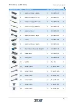
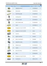
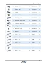
Page 125: ...TCF EVO Line and TCF X Line Spare and wear parts 125 14 9Pneumatics ...

Page 126: ...TCF EVO Line and TCF X Line Spare and wear parts 126 14 10 Sorting pot ...

Page 127: ... level control module Component Pos Designation Pc Article number Art 1 Sensor 1 2000001697 E 2 Shaft vertical 1 1000005232 E 3 Shaft horizontal 1 1000005233 E 4 Control line 1 Integrated in the wiring harness E 5 Stand 1 1000005234 E 6 Mounting bracket 1 1000005235 E ...

Page 128: ...6 E 8 Clamping for sensor 1 1000005237 E 9 Swivel rod 1 1000005238 V 10 Ball bearing 1 2000002120 E 11 Clamping ring 1 1000005239 E 12 Screw M5x16 4 Screw M5x16 E 13 Screw M5x8 6 Screw M5x8 E 14 Screw M5x12 1 Screw M5x12 E 15 Screw M3x8 2 Screw M3x8 E 16 Screw M6x8 1 Screw M6x8 E ...

Page 129: ...nation Pc Article number Art 1 Filter 1 2000002115 E 2 Vacuum generator 1 2000002105 E 3 Connection piece 1 2000002113 E 4 Connection piece 1 2000002114 E 5 Angle plate 1 1000005272 E 6 Sensor 1 2000002106 E 7 Screw M4x8 4 Screw M4x8 E 8 Screw M5x30 2 Screw M5x30 E 9 T connector 1 2000002174 E ...

Page 130: ... Spare and wear parts 130 14 13 Maintenance unit module Component Pos Designation Pc Article number Art 1 Retaining plate 1 1000005258 E 2 Connection 2 2000002102 E 3 Maintenance unit 1 2000002103 E 4 Screw M6x12 2 Screw M6x12 E ...

Page 131: ...TCF EVO Line and TCF X Line Spare and wear parts 131 14 14 Module delivery unit ...

Page 132: ...erved Before disassembly the TCF EVO Line must be shut down For disposal dismantle the TCF EVO Line and disassemble it into the individual material groups Plastics Non ferrous metals e g copper scrap Electrical scrap motors Steel Dispose of the materials in accordance with national legislation Auxiliary materials The following auxiliary materials must be disposed of in accordance with the regulati...

Page 133: ...Original instruction manual ...

Reviews:

Related manuals for TCF EVO Line