background image

2800 Laura Lane  •  Middleton, WI 53562  |  800.288.9383  •  |  www.tcsbasys.com  

33

Introduction

Congratulations on choosing the TCS QD2040C/D series of Ubiquity Cloud Building Managers! This manual covers 

versions C and D of the QD2040 Ubiquity Cloud Building Manager. The QD2040C/D series is a compact, versatile network 

controller that seamlessly connects with Ubiquity Cloud™ via TCSbus or Modbus.
This manual includes all the information you will need to properly install and set up your QD2040C/D. As most units 

come preconfigured, you will most likely only need to read the Installation section of this manual and you can skip the 

Configuration section. 
However, some customers do order their units without being configured beforehand; for those customers, we include the 

comprehensive Configuration section which contains essential information they will need to set up the unit.
If you have any questions regarding your QD2040C/D or your network, contact TCS Technical Support at 800.288.9383, 

ext. 2. Our Technical Support Department hours are Monday – Friday, 7:00 a.m. to 7:00 p.m. (CST). 

Material List

•  QD2040C/D Ubiquity Cloud Site Gateway 
•  External Power Supply
•  Wall Mounting Bracket
• 

Two 120 Ω terminating resistors for RS-485 networks

Mounting

The QD2040C/D is designed to be hung on a wall via the mounting screw holes in each unit. It may also be set on a shelf 

or table. 

If mounting on a wall, do not allow the mounting screws to touch the circuit board inside the enclosure

.

When selecting a location to mount the QD2040C/D, be sure to allow space for cable connections. Locate the QD2040C/D 

away from excessive dust, heat sources, moisture or direct sunlight. The ideal environment is a server room. The 

temperature of the room should not exceed 77ºF (25ºC); good ventilation is mandatory.
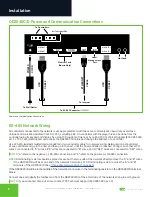
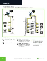
Input Connections

Refer to the 

“QD2040C/D Power and Communication Connections” on page 4

 for the following input connections:

Power:

 Attach the included power supply to the front of the QD2040C/D and insert the power plug into a 120 VAC socket. 

Upon connection the unit should power up automatically. If it does not, press the Power button once. The device will beep 

to confirm it is powering up (model QD2040D only).
Ethernet:

 Connect an Ethernet cable from your network to the Ethernet port labeled Cloud Ethernet 1. Do NOT connect to 

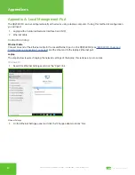
Local Ethernet 2, which is only used for administration or as a fail-over Ethernet port (see 

“Appendix D: Configuring Local 

Management Port as a Failover Port” on page 27

). If you are using a cellular modem, connect the Ethernet cable to the 

Ethernet port on the Cellular Modem.

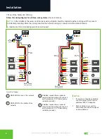
RS-485 Network: Connect an RS-485 network to one of the COM ports. 
USB PORT 1-4 (Optional): Connect an RS-485 network via a USB cable to an RS-485 converter (QD1010), or connect a 

TCS ZigBee network via a wireless gateway (QW1010). 

NOTE:

 The remaining ports on the QD2040C/D are unused or reserved for Admin only.

Installation

Summary of Contents for Ubiquity Cloud QD2040D

Page 1: ...2800 Laura Lane Middleton WI 53562 800 288 9383 www tcsbasys com 202303 Installation Manual Ubiquity Cloud Building Manager QD2040C D...

Page 2: ...on the Network 7 No LAN Link to the Internet 7 No Communication with RS 485 Ports COM 1 and 2 Ubiquity Time Out or No Data 8 Ubiquity Cloud Offline 8 Configuration 9 Introduction 9 Gateway Configurati...

Page 3: ...helf or table If mounting on a wall do not allow the mounting screws to touch the circuit board inside the enclosure When selecting a location to mount the QD2040C D be sure to allow space for cable c...

Page 4: ...es are connected to B wires and all REF wires are connected to REF wires NOTE A refers to the negative RS 485 connection and B refers to the positive RS 485 connection A 120 terminating resistor shoul...

Page 5: ...ring with one end earth grounded 120 terminating resistors provided Shielded twisted three conductor communications wiring with one end earth grounded 120 terminating resistors provided 4 NOTES 1 If u...

Page 6: ...85 port or additional QD1010 adapters 2 Each controller must use the same baud rate and be assigned a unique address Two Wire Network Wiring Follow this wiring diagram for two wire Modbus wiring syste...

Page 7: ...on the Network Make sure the baud rate selection for the QD2040C D is set to match the baud rate of all the controllers on each port network the default communication speed of the serial bus is 9600...

Page 8: ...llow all of the device data logs to be saved 1 Press and release the power button on the front of the device once 2 Wait 10 seconds 3 Listen for a blip sound which indicates the device has shut down N...

Page 9: ...rs upon request It is the customer s responsibility to configure a custom login and password Contact TCS Technical Support 800 288 9383 ext 2 for information on managing Gateway login credentials Gate...

Page 10: ...www ubiquitysystems net by clicking the Set Ubiquity Domain Name button NOTE Secure Sockets Layer SSL requires port 443 outbound to be open Connection Times Default Always On The interval when the uni...

Page 11: ...locations Select whether to enable or disable special options Enter host name if needed typically left blank Network Information The QD2040C D has two Ethernet ports Ethernet Cloud Port 1 and Ethernet...

Page 12: ...fo button Security Information This section contains settings which control the security of the device within the QD2040C D and whether it can be accessed through the web interface If Secure Mode has...

Page 13: ...missioning Tools You can access a separate page containing various commissioning tools by clicking the Commissioning Tools button at the bottom of the Security Information page These tools provide you...

Page 14: ...ction displays the status of the connection between the QD2040C D and the Ubiquity Cloud Server You have three options for the message that will appear here 1 Error No Route to Host The unit does not...

Page 15: ...icular model number and software version Once the update has been downloaded it is automatically applied and the unit will reboot if necessary NOTE The Check for Update command requires that the QD204...

Page 16: ...2800 Laura Lane Middleton WI 53562 800 288 9383 www tcsbasys com 16 16 Configuration Command Line Interface Command Line Interface...

Page 17: ...Ethernet cable Connection Setup Ethernet Cable Connect one end of the Ethernet cable to the Local Ethernet 2 port on the QD2040C D see QD2040C D Power and Communication Connections on page 4 and the o...

Page 18: ...ptions 3 On the Network Connections panel locate the Ethernet interface that is connected to the cable Right click on the item and select Properties Properties 4 On the Ethernet Properties panel locat...

Page 19: ...2800 Laura Lane Middleton WI 53562 800 288 9383 www tcsbasys com 19 19 Appendices TCP IPv4...

Page 20: ...s com 20 20 Appendices 5 On the Internet Protocol Version 4 TCP IPv4 Properties change the IP schema to IP Address 10 248 248 2 Subnet Mask 255 0 0 0 Default Gateway 10 248 248 2 DNS Blank 6 Click on...

Page 21: ...endices 7 Launch any web browser and type in the following address https 10 248 248 1 Device address 8 Depending on your browser s configuration you may get the following screen Privacy Error Warning...

Page 22: ...www tcsbasys com 22 22 Appendices 10 Click on the Proceed link to take you to the next screen Proceed Screen 11 Enter the Login user name and password Login Screen 12 Configure the Gateway as needed...

Page 23: ...t on page 17 and wish to revert back to its previous configuration follow the steps below Windows 10 1 Search for Ethernet Settings and click the Open link Ethernet Settings 2 On the Ethernet Settings...

Page 24: ...leton WI 53562 800 288 9383 www tcsbasys com 24 24 Appendices Properties 4 On the Ethernet Properties panel locate the Internet Protocol Version 4 TCP IPv4 Select that option then click on the Propert...

Page 25: ...25 25 Appendices 5 On the Internet Protocol Version 4 TCP IPv4 Properties General tab 6 Click on the Obtain an IP address automatically radio button 7 Click on the Obtain DNS server automatically rad...

Page 26: ...guration if you are unfamiliar with text based user interfaces Connection Setup 1 Connect the cable to the monitor and to the QD2040C D matching up the corresponding ends HDMI DP See QD2040C D Power a...

Page 27: ...d monitor to the device See Appendix C Monitor and Keyboard on page 26 Hardware Internet Requirements You must provide a secondary Internet connection that is separate from the primary connection Cent...

Page 28: ...ing your IT department before making any changes to the default settings Click on the green Update Application Info button beneath the RS485 Network Port Configuration section to save the failover ser...

Page 29: ...D and reboot the device See Appendix C Monitor and Keyboard on page 26 2 Establish a connection to the CLI see Gateway Configuration via CLI on page 15 3 Skip past the setup questions until you see th...

Page 30: ...2800 Laura Lane Middleton WI 53562 800 288 9383 www tcsbasys com 30 30 Appendices Failover URL Settings E Port 2 Mode Settings...

Reviews: