WCL488 Series Water Cooled Electronic Loads
Operation & Programming Manual
TDI-Dynaload Division
Page 114
402828, Rev. B1
Symptom
Possible Cause
Explanation/Corrective Action
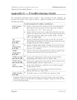
The under voltage switch on the
rear panel is on and the voltage
applied the loads input is less
than 0.6 volts DC.
With the “ UV” switch in the on
position, the load will
“ Load Off” whenever the input
voltage falls below 0.6 volts DC.
Switch the “ UV” switch to the off
position.
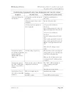
Load powers up but
the “ SYS” and “ UV”
LEDs light red. The
“ DC Load” LED will
not come on.
The voltage applied to the input
of the load may be reversed and
greater than 0.6 volts DC.
Correct the polarity of the load’ s
input DC connection.
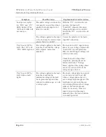
Unit “ Loads Off” by
itself. The “ OV” and
“ SYS” LEDs light red.
The voltage applied to the loads
input has exceeded the voltage
limit setpoint, menu item
number 2.
The load detects DC input voltage
above its over voltage setpoint and
“ Loads Off” for self-protection.
Measure the DC input voltage and
reduce as necessary.
Check the loads voltage limit
setpoint by pressing the menu
button until item 2 “ Voltage
Limit” appears. This voltage limit
can set for zero to 105% of the
voltage range selected.
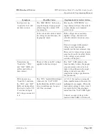
Unit “ Loads Off” by
itself with no fault
lights.
The voltage applied to the loads
input has exceeded the
maximum voltage of the load
for its present range and then
reduced to within range, as with
a voltage spike.
The loads voltage detection circuit
is very fast and will “ Load Off”
when a voltage spike above it’ s
over voltage setpoint appears. The
fault lights do not latch they are
self-resetting. Measure for voltage
spikes at the loads input and
correct as necessary. Once the
input voltage is within range,
manually press the load on button
to resume operation.

