
TDI-Dynaload Division
WCL488 Series Water Cooled Electronic Loads
Operation & Programming Manual
402828, Rev. B1
Page 115
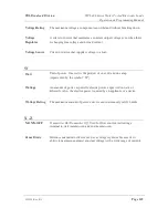
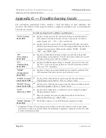
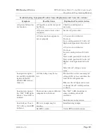
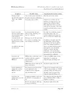
Symptom
Possible Cause
Explanation/Corrective Action
The “ EXT PROG” button or a
range button has been pressed
after setting the current (CI 5
for example).
Pressing the “ EXT PROG” or a
range button will reset the current
to zero. Repeat your required
current entry.
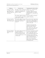
Load powers up,
“ Loads On” but will
not draw current.
In the constant resistance mode,
the voltage sense leads may be
improperly wired.
If the voltage sense read zero
applied voltage, the load will
calculate infinite resistance (zero
current).
Units are shipped with internal
voltage sense lead jumpers
installed on the rear terminal strip.
These can be removed and remote
sense leads can be installed. Refer
to the voltage sense-related
sections of Chapter 1.
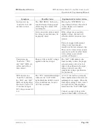
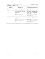
Unit powers up,
“ Loads On” “ SYS”
and “ SAT” LEDs are
yellow and will not
draw current.
There is little or no DC voltage
applied to the loads input.
The “ SAT” LED indicates the
loads inability to draw the proper
set point current, due to lack of
input voltage. Measure the input
voltage; it must exceed the
compliance voltage specification
for your model.
With the unit in a
“ Load On” condition,
the “ SYS” and “ SAT”
LEDs are light yellow.
The load is set for “ CI
0” and has no input
DC voltage connected
to it.
The “ SYS” fault LED will light
whenever the “ SAT” LED
lights. Both these LED’ s under
these conditions can be on or
off. This is normal.
At “ CI 0” the load may normally
leak a small amount of current (30
milliamps for example). When the
loads input voltage is zero, it can’ t
even provide the 30ma leakage
current and the “ SAT” LED lights.
Connect an input voltage to the
load and these LEDs will turn off.


