TDI-Dynaload Division
WCL488 Series Water Cooled Electronic Loads
Operation & Programming Manual
402828, Rev. B1
Page 13
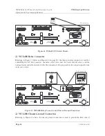
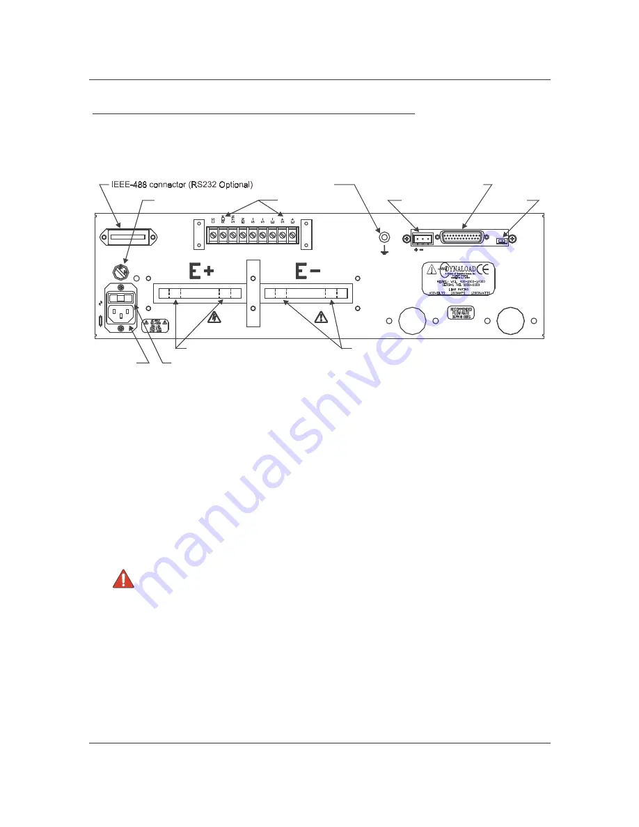
WCL488 Rear Panel Electrical Connections
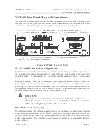
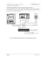
All electrical and electronic connections are made on the unit’s rear panel and are detailed below
in Figure 10. The rear panel also has terminal block connections that are described later in this
section as is an optional equipment wiring diagram using the terminal block connections.
Figure 10. WCL488 Rear Panel Detail
WCL488 E+ and E– Power Input Buses
Install the disconnect relay first. Use the “unswitched” side of the relay as the E+ input. Remove
the S+ to E+ jumper from the terminal block. Add a 22-gauge wire from S+ to the unswitched
side of the relay. It is important to note that voltage must be monitored outside the disconnect
relay.
Referring to Figure 9 and Figure 10, the main DC power inputs are labeled E+ and E– and are the
power input buses for connecting the power source to be monitored or tested. The E+ and E–
power inputs are the two sets of two mounting holes (and related hardware) found on each of the
two input buses located on the left side of the rear of the unit. The input buses are separated by an
insulator for safety and require lugs with a 7/16-inch diameter hole.
CAUTION:
Only the power source-to-load connections are to be made to these buses.
Always be sure these connections are securely tightened. A loose connection
will result in a high temperature at the connection.
WCL488 E+ and E– Wiring Tips
Use the shortest cables that are large enough in cross-section to handle the power source’s current
output. Twist and/or bundle the E+, E– cable(s) as a means of reducing self-inductance. Also, use
lugs to secure the E+, E– cables to the mounting hardware. Connect only the power source to load
cables to the mounting bases; all other connections must be made via the terminal block located
above the buses.
402828-02-07.C D R
AC
SELECT
25
0V
F3
.1
5A
HIGH
CURRENT
IEEE
IEEE
T IGHT EN
SECURELY
FLUID
INLET
RELAY
SLAVE
COMMUNICATION
FL
GND
FLUID
OUT LET
OFF/ ON
UV
AC input
Slave com m unication connector
U V sw itch
Term inal block (9)
Input voltage selector
G round connection
Fuse (fuse holder show n rem oved)
R elay connector
E+ input bus (tw o m ounting holes)
E– input bus (tw o m ounting holes)

