
WCL488 Series Water Cooled Electronic Loads
Operation & Programming Manual
TDI-Dynaload Division
Page 18
402828, Rev. B1
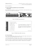
REM (Remote or External Programming)
The REM (Remote Program Input [External Modulation]) terminal is the connecting point for
remote programming from an external programming source. This input is referenced to S–. This
is the remote control input signal. 0 to 10 volts in
yields 0 to full scale loading in whatever mode
and range is selected. When a signal or waveform is presented at this input it will translated
directly into your current level and waveform. The signal source should be referenced to S–.
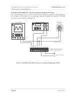
SYN (Synchronized Output Signal)
The SYN (Synchronized Output) terminal supplies a 15V sync signal for triggering external
instrumentation. For instrumentation triggering purposes a 15V square wave synchronous to the
internal pulse generator is supplied. This signal is incorporated on the rear panel terminal block
on WCL488 IEEE models. On non-IEEE models this signal is provided on the front panel. As
with all signals in or out, it is referenced to S (–). The signal is generated with a 10Kohm pull-up
resistor to 15V, and an open collector pull-down to S–. The amplitude of the square wave may be
externally limited without damage to the load. When not in pulse mode, this output remains high
until a current change is executed. At this time, the output is pulsed low for scope triggering.
EN (Remote Enable)
The EN (Remote Enable) terminal is the remote DC enable. Connection between EN and S– must
be connected in order to turn the DC on.
This input is typically used for remote Emergency Power Off (EPO) operation of the DC on/off
function. This input operates in series with the front panel control. If the front panel is in the ON
position, the enable can function to turn the DC on and off.
S– and S+ (Voltage Sense)
There are two S– terminals and one S+ terminal. The S– and S+ (Sense Negative and Sense
Positive) terminals are used to sense the load voltage.
IMPORTANT:
The S+ (Sense Positive) terminal must always be connected on the side of
the disconnect relay that is connected to the source.
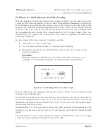
S– and S+ (Voltage Sense) Wiring Tips
The S– and S+ terminals may be connected at the back of the Dynaload, or remotely at the
source. In addition, all input and output signals are referenced to S–. In any single or multiple
load system, S– should be connected to E– (or the negative of the source)
at one and ONLY one
point.
CAUTION:
Damaging current loops could result from multiple connections to E–.
S– must only be connected to the E– source at the master Dynaload in a master/slave (parallel)
configuration. The D connector cable(s) between master and slave(s) provide the S– loop to the


