

WCL488 Series Water Cooled Electronic Loads
Operation & Programming Manual
TDI-Dynaload Division
Page ii
402828, Rev. B1
CS (Current Sample)...........................................................................................17
REM (Remote or External Programming)..........................................................18
SYN (Synchronized Output Signal) ...................................................................18
EN (Remote Enable)...........................................................................................18
S– and S+ (Voltage Sense) .................................................................................18
S– and S+ (Voltage Sense) Wiring Tips ......................................................18
E– and E+ (Input) ...............................................................................................19
WCL488 Terminal Block Connections Optional Equipment Wiring.................20
Recommended Operating Procedure.................................................................21
Operating Mode Guidelines................................................................................22
CI — Constant Current Mode (Basic Mode)...........................................................22
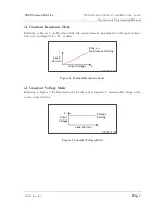
CR — Constant Resistance Mode (Basic Mode).....................................................22
CV — Constant Voltage Mode (Basic Mode).........................................................23
CP — Constant Power Mode (Basic Mode)............................................................23
Short Circuit ............................................................................................................23
MEM — Memory Recall Locations........................................................................23
Manual Adjust .........................................................................................................23
Remote Programming..............................................................................................23
Local Control...........................................................................................................24
Fault Indicators........................................................................................................24
Undervoltage Lockout .............................................................................................25
Programmable Under Voltage .................................................................................25
Menu Commands.....................................................................................................26
Current Limit Setting..........................................................................................27
Range Switching and Current Limit Set Point....................................................27
Voltage Limit Setting .........................................................................................27
Power Limit Setting............................................................................................27
Slew Rate Adjustment ........................................................................................27
Encoder Resolution Setting ................................................................................27
Front Panel Configuration Memory Set .............................................................28
Front Panel Lock ................................................................................................28


