TDI-Dynaload Division
WCL488 Series Water Cooled Electronic Loads
Operation & Programming Manual
402828, Rev. B1
Page 41
WCS AC Input
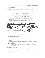
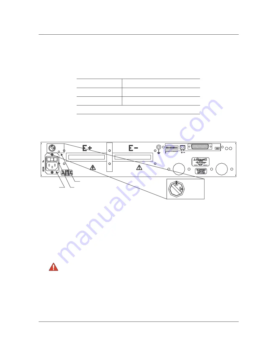
This connection provides the Dynaload with its operating power and its safety ground (refer to
Figure 21). Power requirements are user selectable and described below in Table I.
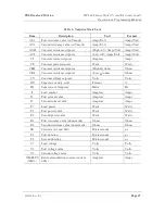
Table I. Input Power Requirements
Switch Setting
Operation Range
110V
103.5 Vac – 126.5Vac at 1.5A
220V
187 Vac – 242Vac at 0.8A
NOTE: The operational frequency range is 47Hz – 63Hz.
NOTE:
Each WCS (slave)
MUST be set the same as the master WCL488.
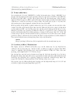
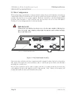
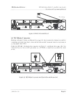
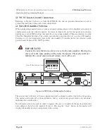
Figure 21. WCS. AC Input, Fuse and Input Voltage Selector
WCS Input Voltage Selector
The Input Voltage Selector (refer to Figure 21) is mounted on the rear panel immediately above
the AC input and fuse assembly.
NOTE:
Each WCS (slave) Input Voltage Selector
MUST be set the same as the master WCL488.
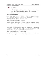
WARNING:
Ensure that the power cord is removed before making changes to the
voltage selector tab.
WCS AC Input Wiring Tips
A standard U.S. three-prong cord is provided with your Dynaload. The Input Voltage Selector is
mounted above of the three-prong AC connector and fuse (see Figure 21 and refer to the
WCS
Input Voltage Selector
section that follows).
25
0V
HIGH
CURRENT
T IGHT EN
SECURELY
AC
SELECT
F3
.1
5A
OFF/ ON
UV
FLUID
OUT LET
RELAY
FLUID
INLET
GND
A
3
SLAVE
ADDR
O
N
A
0
A
2
A
1
A
9
A
8
A
7
A
6
A
4
A
5
SLAVE
COMMUNICATION
402828-02-15.C D R
AC input
Fuse (fuse holder show n rem oved)
Input voltage selector
AC
SELECT

