
WCL488 Series Water Cooled Electronic Loads
Operation & Programming Manual
TDI-Dynaload Division
Page 42
402828, Rev. B1
WARNING:
The power cord provides a chassis ground through a third conductor. Make
sure that your power outlet is of the 3-conductor type with the correct pin
connected to earth ground. Always Connect the AC cord first to your
Dynaload and THEN to the utility outlet.
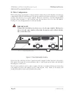
WCS Fuse Replacement
Referring to Figure 21, the AC input fuse is located above the AC Input and below the Input
Voltage Selector. The fuse replacement part numbers for the Dynaload are MDA-3 (3 Amp, 250
Volt, slow blow, 1-1/2 inch American version) or equivalent
OR GDC-3.15A-250V (3.15 Amp,
250 Volt, slow blow, 20 mm European version) or equivalent.
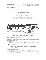
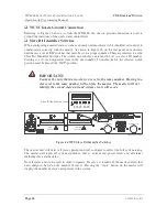
WCS Slave Communication Connector
This DB25 “ D” connector is located in the upper right corner of the rear panel and is used for
synchronized parallel Dynaload operation (see Figure 20). This connector is labeled “ SLAVE
COMMUNICATION” .
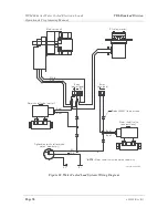
WCS Slave Communication Connector Wiring
This 25-pin “ D” connector is used to link the WCS slave units to the master units (and vice
versa). If you are purchasing cables, be sure the PIN configuration is always 1 to 1 (not all cables
are provided this way and a crossover of PINS will cause erroneous operation).
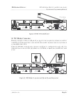
WCS UV (Undervoltage Lockout) Switch
Referring to Figure 22, the UV switch has two positions, ON and OFF. This switch is described
in detail in the
Undervoltage Lockout
section later in this chapter.


