TDI-Dynaload Division
WCL488 Series Water Cooled Electronic Loads
Operation & Programming Manual
402828, Rev. B1
Page 43
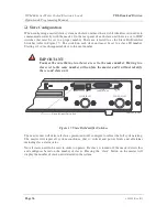
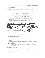
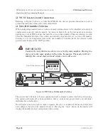
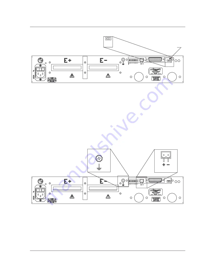
Figure 22. WCS UV Switch Detail
WCS Relay Connector
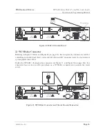
Referring to Figure 23 below and Figure 18 (on page 38), this two-pin relay connector is used for
controlling each individual slave’ s water shutoff valve and DC disconnect relay in a high current
system greater than 1200A.
Unlike the WCL488’ s three-pin relay connector (see Figure 13, and Figure 18 [on page 38]), this
connector does not have an FL pin (which on a WCL488, or master unit, controls the water
servo).
Figure 23. WCS Relay Connector and Chassis Ground Connection
25
0V
HIGH
CURRENT
T IGHT EN
SECURELY
AC
SELECT
F3
.1
5A
OFF/ ON
UV
FLUID
OUT LET
RELAY
FLUID
INLET
GND
A
3
SLAVE
ADDR
O
N
A
0
A
2
A
1
A
9
A
8
A
7
A
6
A
4
A
5
SLAVE
COMMUNICATION
402828-02-17.C D R
R elay connector
G round connection
GND
RELAY
25
0V
HIGH
CURRENT
T IGHT EN
SECURELY
AC
SELECT
F3
.1
5A
OFF/ ON
UV
FLUID
OUT LET
RELAY
FLUID
INLET
GND
A
3
SLAVE
ADDR
O
N
A
0
A
2
A
1
A
9
A
8
A
7
A
6
A
4
A
5
SLAVE
COMMUNICATION
402828-02-16.C D R
UV switch
OFF/ ON
UV

