
TDI T
URBO
T
WIN
FROM
TECH DEVELOPMENT
Publication T1-932
Page: i
Issued May 20, 2016
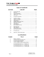
TABLE OF CONTENTS
SECTION
SUBJECT
PAGE
1.0
General
Information ............................................................................... 1
1.1
Description
.............................................................................................
1
1.2
Product
Identification ............................................................................. 1
1.3
Physical
Characteristics
......................................................................... 2
1.4
Performance
..........................................................................................
2
2.0
Orientation
of the Starter ....................................................................... 2
3.0
Installing
the Starter ............................................................................... 2
3.1
Supply
Line
Installation .......................................................................... 3
3.2
Inlet
Pressure Port ................................................................................. 3
3.3
Exhaust
Piping ....................................................................................... 4
3.4
Soft Start Valve & Filter Fitting .............................................................. 4
3.5
Natural
Gas
Installation ......................................................................... 4
3.6
Piping
System ........................................................................................ 4
3.7
Atex
Applications ................................................................................... 4
3.8
Best Installation Practices ...................................................................... 5
4.0
Starter
Operation ................................................................................... 6
4.1
Basic
Operation
.....................................................................................
6
4.2
Automated Start Panel ........................................................................... 7
4.3
Best
Operating Practices ....................................................................... 7
5.0
T00-VE
Warranty ................................................................................... 7
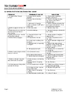
6.0
Operator’s
Troubleshooting Guide ........................................................ 8
ILLUSTRATIONS
FIGURE
TITLE
PAGE
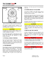
1
Direction of Rotation…………………….. ................................................. 2
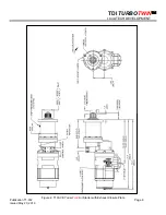
2
T100-VE with Exhaust Closure Plate ...................................................... 9
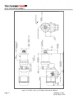
3
T100-VE with Exhaust Deflector…………….. ........................................ 10
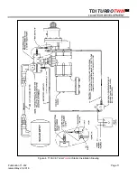
4
T100-VE
Installation
Drawing…………….. ............................................ 11
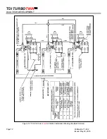
5
T100-VE Installation Drawing (Multiple Starters)……….. ...................... 12
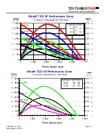
T112-VE
Performance
Curve – 12 nozzles (air).................................... 13
T121-VE
Performance
Curve – 21 nozzles (air).................................... 13
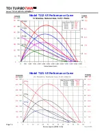
T112-VE
Performance
Curve – 12 nozzles (gas) .................................. 14
T121-VE
Performance
Curve – 21 nozzles (gas) .................................. 14


