background image

TDI TURBO

TWIN


                                                                                                                          FROM 

TECH DEVELOPMENT


Publication 

T1-932 


  Page 

Issued May 20, 2016


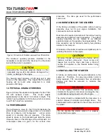
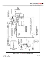
3.1 SUPPLY LINE INSTALLATION 


WARNING


Be sure to either bleed the pressurized air reservoir 
and/or safety the system such as closing all valves 
prior to installing any starter supply line. 


T100-VE

 starters come standard with a 2" NPT female 

pipe thread for the inlet connection port

.

  The supply line 

consists of the line from the air source, a pressure 
regulator (when necessary), a manual or relay valve, 
and the connection to the starter inlet. Hard piping may 
be used, but a section of flexible tubing should be 
installed at the starter to prevent leaks due to engine 
vibration. 
 
Care must be taken to ensure that all inlet supply line 
piping is no less than 1.5” and that all components used 
are capable of passing the required air flow. 


NOTE 

 Valves with a Cv of 40 or higher is recommended. 


If the supply line must be longer than 20 feet, the inlet 
supply line piping should be increased to 2" in diameter 
to ensure proper performance by your

 T

URBO

T

WIN

 
Because turbine starters such as the 

T100-VE

 are 

sensitive to flow restrictions, care must be taken to use 
uniform hose or tubing and fittings for connection of the 
supply line.  Tees, elbows and line length must be kept 
to a minimum.  TDI recommends that hose or flex 
couplings be installed to eliminate possible leakage 
caused by strain on the supply line. 
  
Normally, an air strainer is not required. In dirty 
environments, use of a #40 mesh Y-strainer is 
recommended. The 

T100-VE

 is highly tolerant of dirt in 

the air line, however, starter life can be increased with 
the use of an air strainer. 
 
A pressure regulator is required when the air supply 
pressure is great enough to exceed the starter operating 
pressure (at the inlet port) and/or the maximum torque. 
 
A manual ball valve may be used to admit drive air/gas 
to the starter. The manual valve should be located in a 
safe position away from the engine.  
 
A preferred valve is pilot-operated, which can be 
pneumatically or electrically actuated. The valve should 
be located close to or even on the starter inlet for best  

 
performance. Pneumatic or electrical control lines may 
be routed virtually anywhere for the customer's preferred 
operating station. This type of valve actuates from a fully 
closed to a fully open position very rapidly. TDI offers a 
variety of relay valves such as P/N RLVA-25683-001-2-
01, which is a 1-1/2" port, pneumatically actuated valve. 
 
The supply line should be dry-fitted for proper 
alignment/location prior to final assembly. All pipe- 
threaded joints should be sealed with Loctite Pipe 
Thread Sealant (TDI P/N 9-94085) or equivalent for leak 
tight joints prior to final assembly. Be sure to tighten all 
joints to proper torque after final assembly. 
 

CAUTION 

In cold weather climates, care should be taken while 
designing your installation to prevent condensation 
from developing in the starter system.  In systems 
with a regulator valve or relay valve, there is the 
possibility of freeze-ups.


A tee connection with a quick disconnect can be added 
to the inlet.  This will allow an external air source to be 
used to accomplish a “blow start” if the system freezes. 
Once the engine has been started, the other system 
components may be thawed.  
 

CAUTION 

On new installations, it is strongly recommended to 
blow out the supply line with air to remove possible 
dirt and welding slag prior to final connection to the 

T

URBO

T

WIN

 starter.  Be sure to secure the free end 

of the supply line prior to blowing out the line.


3.2 INLET PRESSURE PORT


A 1/4" NPT port is located on the air inlet. This port may 
be used to check the supply pressure at the starter when 
the starter is operating. Remove the 1/4" NPT pipe plug 
and save for later use. Install 1/4" minimum size tubing 
to the port. Route the tubing away from the starter to a 
safe location away from the engine. Install a pressure 
gauge on the tubing. This pressure monitoring 
line/gauge may be permanently installed. Use Loctite 
Pipe Thread Sealant or equivalent. Alternately, a 
pressure transducer may be installed at the pressure 
check port and electrical lines routed to a digital display 
at the operator's station. 
 
This pressure port is invaluable in diagnosing air starter 
and/or installation problems. 
 

Summary of Contents for TURBOTWIN T100-VE

Page 1: ...velopment 6800 Poe Ave Dayton OH 45414 Tel 937 898 9600 Fax 937 898 8431 Website tdi turbotwin com Publication T1 932 Dated May 20 2016 INSTALLATION AND OPERATING MANUAL MODEL T100 VE TURBOTWIN Engine Air Starters ...

Page 2: ...tion 4 3 6 Piping System 4 3 7 Atex Applications 4 3 8 Best Installation Practices 5 4 0 Starter Operation 6 4 1 Basic Operation 6 4 2 Automated Start Panel 7 4 3 Best Operating Practices 7 5 0 T00 VE Warranty 7 6 0 Operator s Troubleshooting Guide 8 ILLUSTRATIONS FIGURE TITLE PAGE 1 Direction of Rotation 2 2 T100 VE with Exhaust Closure Plate 9 3 T100 VE with Exhaust Deflector 10 4 T100 VE Instal...

Page 3: ...d air means either compressed air or natural gas 1 1 DESCRIPTION The T100 VE features three basic subassemblies a unique two stage turbine motor section an offset spur gear assembly and a pre engage drive assembly The two stage motor section features greater stall torque than a single stage turbine plus aerodynamic speed control This aerodynamic speed control helps protect the T100 VE starter from...

Page 4: ... for the performance curve is air 2 0 ORIENTATION OF THE STARTER If the factory orientation of the starter turbine housing assembly does not fit your engine installation this component can be re oriented Determine the required orientation of the turbine housing assembly and gearbox housing assembly The turbine housing assembly can be rotated to six different positions relative to the gearbox housi...

Page 5: ...ted The valve should be located close to or even on the starter inlet for best performance Pneumatic or electrical control lines may be routed virtually anywhere for the customer s preferred operating station This type of valve actuates from a fully closed to a fully open position very rapidly TDI offers a variety of relay valves such as P N RLVA 25683 001 2 01 which is a 1 1 2 port pneumatically ...

Page 6: ...108 for additional information regarding obsoleting of the soft start P N 2 28243 and filter fitting P N 2 28270 CAUTION For maximum pinion life and full warranty coverage the soft start valve P N 2 28243 MUST be installed in the applied pressure port APP of the relay valve 3 5 NATURAL GAS INSTALLATION The installation of the starter using natural gas is similar to the air installation except all ...

Page 7: ...hese special conditions must be followed for the starter to conform to the ATEX Directive and for the ATEX Declaration of Incorporation to be valid 3 8 BEST INSTALLATION PRACTICES Wear protective gloves and steel toe shoes when installing air starter Follow engine manufacturer s torque requirements for all starter attachment screws For new installations or where new piping or receiver tanks are in...

Page 8: ...iven in this manual Consult your TDI distributor if you have exhaust plumbing that creates back pressure and reduces starter performance You may be able to increase the supply pressure to restore the lost power Follow the engine manufacturer s instructions for starting the engine CAUTION The grease used in the planetary system has a shelf life of 2 years Therefore if the starter is NOT installed a...

Page 9: ...n be best measured dynamically while starter is running For longer starter life operate or design controls to shut off supply pressure to the air starter immediately after a successful engine start If engine fails to start or stalls wait at least 15 seconds before attempting to re start to allow the starter to coast to a complete stop Never re engage pinion into ring gear when starter is coasting ...

Page 10: ...ot engage A Air pressure is too low A Increase air pressure to 40 150 psig B Control lines to starter ports reversed B Check installation diagram and correct C Solenoid valve not operating or plugged C Check wiring and solenoid operation Correct wiring remove blockage or replace solenoid valve as needed D Damaged pinion teeth D Replace pinion or starter drive as necessary 6 Starter runs but engine...

Page 11: ...TDI TURBOTWIN FROM TECH DEVELOPMENT Publication T1 932 Page 9 Issued May 20 2016 Figure 2 T100 VE TURBOTWIN Air Starter with Exhaust Closure Plate ...

Page 12: ...TDI TURBOTWIN FROM TECH DEVELOPMENT Page 10 Publication T1 932 Issued May 20 2016 Figure 3 T100 VE TURBOTWIN Air Starter with Exhaust Deflector ...

Page 13: ...TDI TURBOTWIN FROM TECH DEVELOPMENT Publication T1 932 Page 11 Issued May 20 2016 Figure 4 T100 VE TURBOTWIN Air Starter Installation Drawing ...

Page 14: ...TDI TURBOTWIN FROM TECH DEVELOPMENT Page 12 Publication T1 932 Issued May 20 2016 Figure 5 T100 VE TURBOTWIN Air Starter Installation Drawing Multiple Starters ...

Page 15: ... Compressed Air 9 25 1 Ratio Inlet Pressure SCFM Nm3 h 90 psig 1606 2730 60 psig 1158 1969 40 psig 848 1442 TORQUE POWER 0 10 20 30 40 50 60 70 0 50 100 150 200 250 300 350 0 1 000 2 000 3 000 4 000 5 000 Pinion Speed rpm 150 psig 90 psig 60 psig 120 psig 0 7 5 14 9 22 4 29 8 37 2 44 8 52 2 0 68 136 204 272 340 408 476 Hp Kw Nm lb ft Model T112 V Performance Curve 12 Nozzles Compressed Air 9 25 1 ...

Page 16: ...TDI TURBOTWIN FROM TECH DEVELOPMENT Page 14 Publication T1 932 Issued May 20 2016 Model T112 VE Performance Curve Model T121 VE Performance Curve ...

Reviews: