TDI T
URBO
T
WIN
™
FROM
TECH DEVELOPMENT
Page
Publication T30-729, Rev. 2
Issued April 15, 2006
2
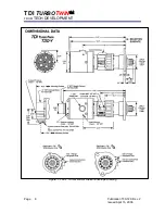
B. Note that the mounting flange assembly
can be rotated to twelve different positions
relative to the gearbox assembly (control
ports) and the gearbox housing assembly
can be rotated to four positions relative to
the inlet port. Additionally, the optional
exhaust housing can be rotated to eight
positions relative to the inlet port.
CAUTION
All screw threads are treated at the factory
with a fastener retention compound. Every
screw and tapped hole must be clean and
have a drop of Loctite 290 applied to the
threads before being reinstalled.
2.1.1 Pinion Housing Assembly Re-
Orientation
Remove the twelve mounting flange
attachment socket head cap screws.
Rotate the mounting flange to the desired
position and reinstall the twelve socket head
cap screws. Torque the twelve screws to
9.4 Lb-Ft. (12.7 Nm).
CAUTION
Ensure that the O-ring on the mounting
flange remains in position and is not cut.
2.1.2 Gearbox Assembly Re-Orientation
Remove the four tie bolts that secure the
gearbox assembly to the inlet assembly.
Rotate the gearbox housing / pinion housing
assembly to the desired position.
WARNING
Do not remove the five radial screws that
connect the inlet and turbine housing. The
inlet and turbine housing assembly must
remain in the same position, relative to each
other.
CAUTION
Ensure that the O-ring on the gearbox
assembly remains in position and is not cut.
Reinstall the four tie bolts. Torque the four
tie bolts to
9.4 Lb-Ft. (12.7 Nm).
CAUTION
Because of the length of the tie bolts, too
much torque may weaken or break them.
DO NOT OVER-TORQUE.
2.1.3 Inlet Assembly Orientation
Refer to Section 2.1.2.
After removing the four tie bolts, rotate the
inlet assembly to the desired position
relative to the control ports on the gearbox.
Align the components and reassemble per
Section 2.1.2.
CAUTION
Ensure that the O-ring on the gearbox
assembly remains in position and is not cut.
2.2 Model T30-U Flange Mount
Orientation
A. Determine the required orientation of the
flange assembly, gearbox assembly, and
any optional exhaust port.
B. Note that the mounting flange assembly
can be rotated to twelve different positions
relative to the gearbox assembly (control
ports) and the gearbox housing assembly
can be rotated to four positions relative to
the inlet port. Additionally, the optional
exhaust housing can be rotated to eight
positions relative to the inlet port.
CAUTION
All screw threads are treated at the factory
with a fastener retention compound. Every
screw and tapped hole must be clean and
have a drop of Loctite 290 applied to the
threads before being reinstalled.
2.2.1 Mounting Flange Re-Orientation
Remove the twelve mounting flange to
pinion housing assembly socket head cap
screws.

