U L T R A F L E X H D P D U U S E R M A N U A L
3.7.2
48V DC Output
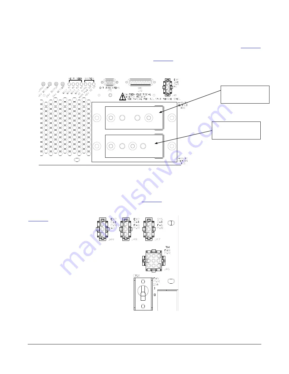
The main 48V output bus bars are located on the rear of the PDU under a protective cover. Refer to
for a view of the DC output bus bars with the cover removed. The 48V output bus (positive) is on the top and
the 48V return bus (negative) is on the bottom as shown in
. To prevent incorrect connections to the
bus bars, the center-to-center spacing is 1.0” on the output bus and 1.375” on the return bus.
Figure 16 – 48V DC output bus bars
3.7.3
Fan Power
Connectors for the Test Head Fantray, system cabinet fan, expansion cabinet fan and expansion cabinet power
vault are provided on the rear of the PDU. Refer to
for a view of fan connectors J46, J47, J48 and
expansion cabinet power vault connector J49. Pinout details for each connector are provided below. Power to
the fan connectors is protected by a 15A circuit breaker CB10 located below the fan connectors as shown in
Figure 17 – Fan power connectors
708401 Rev B
Page 23 of 38
48V Output bus
(positive)
48V Return bus
(negative)


