U L T R A F L E X H D P D U U S E R M A N U A L
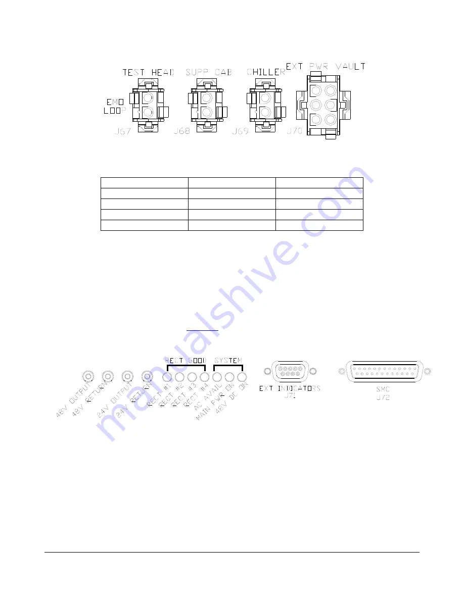
Figure 21 – EMO loop connectors
EMO location
Connector number
Supplied with PDU
Test head
J67
No
Support Cabinet
J68
No
Chiller J69 No
External Power Vault
J70
Yes
Table 12 – EMO connectors
3.9
Monitor & Control
Monitoring and control of the PDU is accomplished via the interface PCB mounted at the rear of the PDU.
The interface PCB contains test points, alarm LED’s and connections for external alarms and the SMC. The
interface PCB also contains a filter for the 48V DC fan output and connections for the EMO loop. See below
for details on the interface PCB. Refer to
for a detailed view of the interface PCB connections on the
rear of the PDU.
Figure 22 – Interface PCB connections
708401 Rev B
Page 27 of 38


