U L T R A F L E X H D P D U U S E R M A N U A L
3.5
AC Distribution
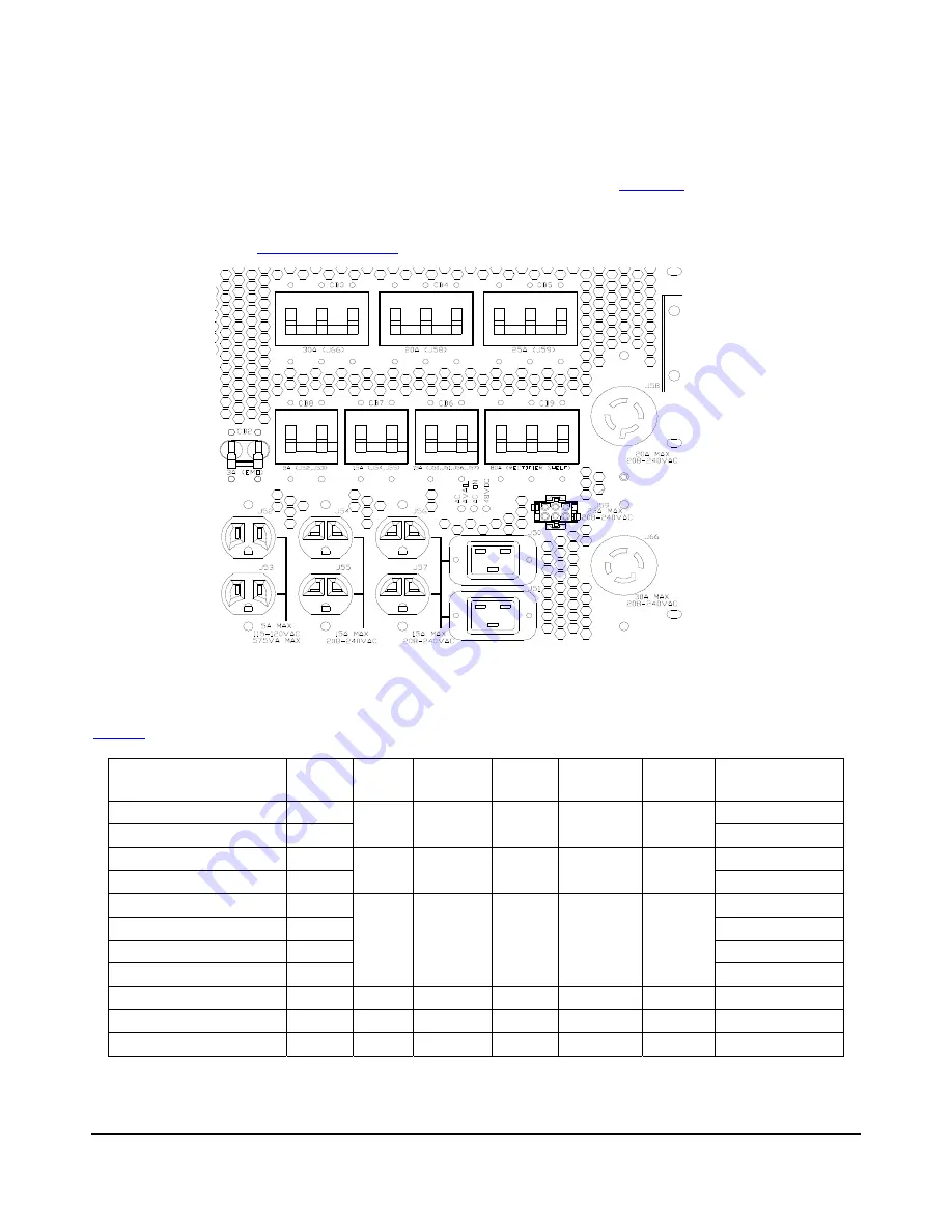
All the AC distribution is provided on the front panel of the PDU. Refer to
AC distribution. The AC loads are distributed as evenly as possible across the three phases. The system wiring
is optimized for the least current phase imbalance for the system. For more detailed information on the AC
distribution refer to the
drawing.
Figure 14 – Detail view of AC distribution
3.5.1
AC connectors
below details the specifications on the AC distribution connectors.
Use
Outlet
Number
Circuit
Breaker
Breaker
Rating (A)
# phases
Used
Phases
Voltage
(VAC)
Connector type
External IEC
J52
5-15R
External IEC (DSP)
J53
CB8
5
2
B & C
115
5-15R
External IEC Spare
J54
6-15R
External IEC Spare
J55
CB7
15
2
B & C
208-230
6-15R
SMC J50
60320-C20
Spare J51
60320-C20
Manipulator J56
6-15R
Spare J57
CB6
15
2
A & B
208-230
6-15R
Expansion Cabinet Vault J58
CB4
20
3
A, B & C 208-230
L15-20R
CDU
J59
CB5
25
3
A, B & C 208-230 Amp mate-n-lok
DC-PM
J66
CB3
30
3
A, B & C 208-230
L15-30R
Table 5 – AC Distribution details
708401 Rev B
Page 20 of 38


