background image

PAH300

350S24

-SERIES 

TDK-Lambda 

9


is within specified maximumoutput power.   
Furthermore,  reduce noise  effect  by using  shield  wire, 
twist pair, or parallel pattern. 
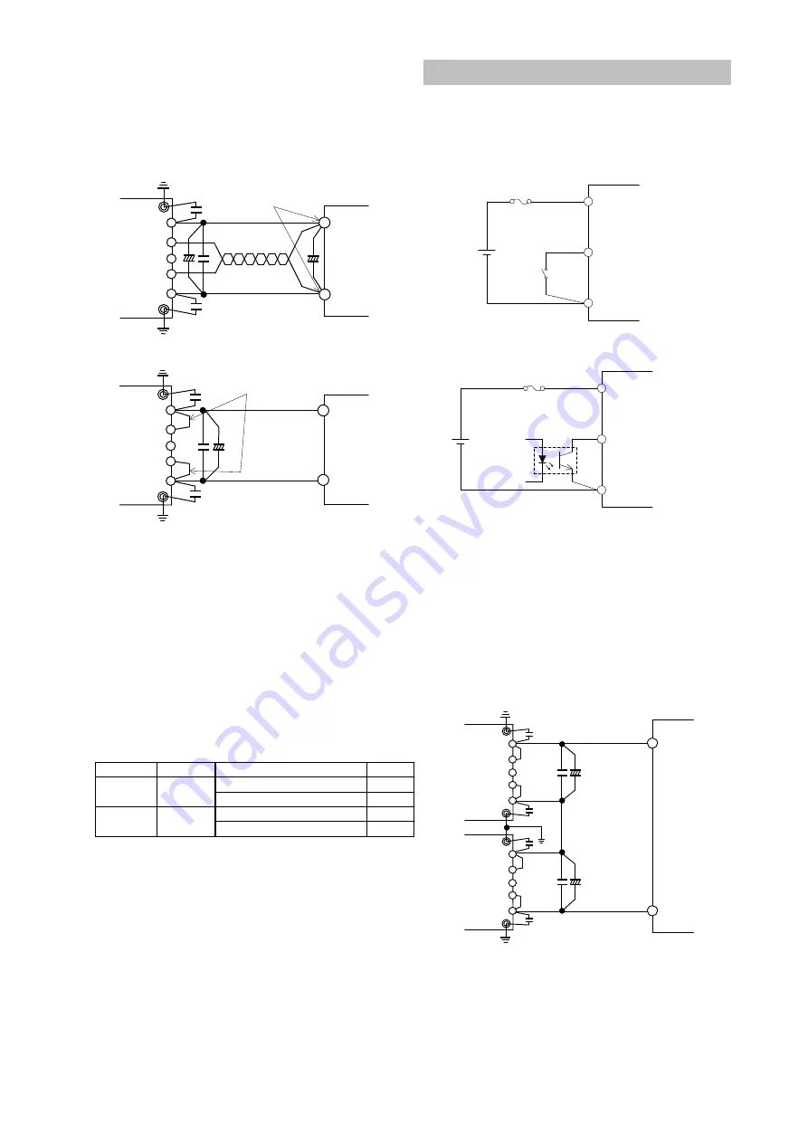
 

Load

Stabilize the output voltage

+

-

+V

-V

-S

+S

+

+

TRM

at load terminals


Fig.9-1 Remote Sensing is in Use 


Load

Stabilize the output voltage

+

-

+V

-V

-S

+S

+

TRM

at output terminals


Fig.9-2 Remote Sensing is Not in Use 


10. ON/OFF Control (CNT terminal) 

  Without  turning  the  input  supply  on  and  off,  the 
output  can  be  enabled  and  disabled  using  this 
function.  This  function  also  can  be  used  for  output 
sequence of plural power modules. 
  There are two kinds of logic control, Negative logic 
control  and  Positive  logic  control,  depend  on  the 
option selected. 
  ON/OFF  control  circuit  is  on  the  primary  side  (the 
input  side).  For  secondary  control,  isolation  can  be 
achieved through the use of an opto-coupler or relay. 


  Notes 

    1.  When  ON/OFF  control  function  is  not  used  for 

the Standard and /T option, CNT terminal should 
be shorted to –Vin terminal. 

    2.  When  ON/OFF  control  function  is  not  used  for 

the  /P  option  and  /PT  option,  CNT  terminal 
should be opened. 

    3. When using long wiring, for prevention of noise, 

attach  a  0.1µF  capacitor  between  CNT  terminal 
and –Vin terminal. 

    4.  At  L  level,  maximum  source  current  from  CNT 

terminal to –Vin terminal is 0.5mA


    5. The maximum CNT terminal voltage is 35V. 


(1)


Output ON/OFF control 


Fig.10-1 CNT Connection (1) 


(2)


Secondary (output side) control 


Fig.10-2 CNT Connection (2) 


11. Parallel Operation 

  Parallel Operation can not be used. 


12. Series Operation 

  Series  operation  is  possible  for  PAH300

350S24 

series.  Connections  shown  fig.  12-1  and  fig.  12-2  are 
possible. 

+

+

+

-

Load

+V

+S

-S

-V

TRM

+V

+S

-S

-V

TRM


Fig.12-1 Series Operation due to High Output 

Voltage 

Logic

CNT Terminal Level to -Vin Terminal

Output status

Standard 

H Level (4V

H

35V) or Open

OFF

/T option

L Level (0V

L

0.8V) or Short

ON

/P option

H Level (4V

H

35V) or Open

ON

/PT option

L Level (0V

L

0.8V) or Short

OFF

Negative Logic

Positive Logic

+Vin

CNT

-Vin

Transistor, Relay
or Equivalent

PAH200H

series

Power 
module 

+Vin

CNT

-Vin

Secondary
(output side)

PAH200H

series

Power 
module 

Summary of Contents for 350S24 Series

Page 1: ...ionon electronic equipment For input terminalsof24 V inputmodels apply avoltagefromaprimary sourcewith reinforced ordouble insulation Output voltage of this product is considered to have hazardous ene...

Page 2: ...TP 9 Remote Sensing S S terminal 10 ON OFF Control CNT terminal 11 Parallel Operation 12 Series Operation 13 Operating Ambient Temperature 14 Operating Ambient Humidity 15 Storage Ambient Temperature...

Page 3: ...lter Baseplate CASE Switching Frequency fixed 330kHz typ Sequence Time Chart For Standard Model with Negative logic for ON OFF control Input Voltage Output Voltage 1 ON OFF Control L H 0V Vin 0V Vout...

Page 4: ...rminal CASE Baseplate Terminal S Remote Sensing Terminal CNT ON OFF Control Terminal TRM Output Voltage Trimming Terminal Vin Input Terminal S Remote Sensing Terminal V Output Terminal Baseplate can b...

Page 5: ...connect electrolytic capacitor or ceramic capacitor between Vin and Vin terminals Furthermore use electrolytic capacitor with small ESR value Especially take note that during line turn off at low amb...

Page 6: ...y that ripple current does not exceed allowable ripple current before use C5 0 1 F To reduce spike noise voltage at the output connect a ceramic capacitor between V and V within 50mm distance from the...

Page 7: ...ut and output wiring method as well as peripheral circuits When selecting input filter be sure to verify actual EMI characteristics CE and RE before finalizing the filter Refer to PAH300 350S24 Evalua...

Page 8: ...output voltage higher 2 1 Allowable maximum output current maximum output power output voltage reduce maximum output current in specification 2 2 Connect an external resistor Radj up between TRM term...

Page 9: ...note that power module might be damaged continuing output short circuit or over load conditions depending on thermal conditions 7 OverVoltageProtection OVP This power module has built in OVP function...

Page 10: ...l should be shorted to Vin terminal 2 When ON OFF control function is not used for the P option and PT option CNT terminal should be opened 3 When using long wiring for prevention of noise attach a 0...

Page 11: ...gh care when storing the power module because rust which causes poor solderability would form in each terminal when stored in high temperature high humidity environment 17 Cooling Method Operating tem...

Page 12: ...g a resistor etc DC Isolation Tester Vin CASE CNT Vin V S TRM S V Over 100M at 500VDC Fig 20 1 Isolation Test 21 Vibration Vibration of power module is defined in case of mounting on printed circuit b...

Page 13: ...m Land diameter 3 0 mm Output terminals 2 0 mm Hole diameter 2 5 mm Land diameter 4 5 mm Mounting Holes FG Hole diameter 3 5 mm Land diameter 5 5 mm For position of the holes see outline drawing of th...

Page 14: ...l 3 5 Non threaded hole 2 2 Standard model and Poption model M3 Threaded hole 3 Regarding Vibration The vibration specification of the module is determined assuming that only the power module is mount...

Page 15: ...ts For cases where output voltage adjustment is used is the resistor or volume setting connections correctly done 3 Output voltage is low Is specified input voltage applied Are the remote sensing term...

Reviews: