background image

PAH300

350S24

-SERIES 

TDK-Lambda 

10


+

+

+

-

Load

Load

+

-

+V

+S

-S

-V

TRM

+V

+S

-S

-V

TRM


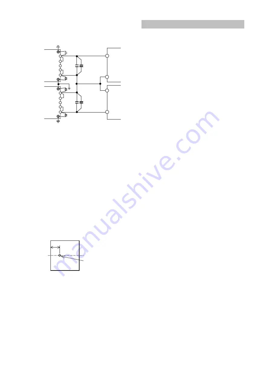
Fig.12-2 Series Operation due to 

±

Output 


13. Operating ambient Temperature 

  There is no restriction on mounting direction but there 
should be enough consideration for airflow so that heat 
does not accumulate around the power module vicinity. 
Determine  external  components  configuration  and 
mounting  direction  on  PCB  such  that  air  could  flow 
through the heatsink at forced cooling and conventional 
cooling.   
  By  maintaining  actual  baseplate  temperature  below 
100

, operation is possible. 

  For  details  on  thermal  design,  refer  to  Application 
Notes “Thermal Design”.   
 
Note :   
  Maximum  baseplate  temperature  is  100

.  For  worst 

case  operating  condition,  verify  baseplate  temperature  at 
measurement point indicated in fig. 13-1. 


Measurement Point
of Baseplate
Temperature

21mm

Input Side

Output Side

CL


Fig.13-1 Measurement Point of   

Baseplate Temperature 


  For  better  improvement  of  power  module  reliability, 
derating  of  baseplate  temperature  when  using  is 
recommended. 


14. Operating Ambient Humidity 

  Take  note  that  moisture  could  lead  to  power  module 
abnormal operation or damage. 
 

15. Storage Ambient Temperature 

  Abrupt  temperature  change  would  cause  moisture 
formation  that  leads  to  poor  solderabilty  of  each 
terminal of the power module. 


16. Storage Ambient Humidity 

  Take  enough  care  when  storing  the  power  module 
because rust which causes poor solderability would form 
in  each  terminal  when  stored  in  high  temperature,  high 
humidity environment. 


17. Cooling Method 

  Operating  temperature  range  is  specified  by  the 
baseplate  temperature.  Therefore,  several  methods  of 
heat dissipation are possible. 
  For details on thermal design, refer to Application Notes 
“Thermal Design”. 


18. Baseplate Temperature vs. Output   

Voltage Drift 

  Output  voltage  drift  is  defined  as  the  rate  of  voltage 
change when baseplate temperature only is changed during 
operation. 


19. Withstand Voltage 

  This  power  module  is  designed  to  have  a  withstand 
voltage  of  1.5kVDC  between  input  and  baseplate, 
1.5kVDC  between  input  and  output  and  500VDC 
between  output  and  baseplate  for  1  minute.  When 
conducting  withstand  voltage  test  during  incoming 
inspection,  be  sure  to  apply  DC  voltage.  Also,  set  the 
current  limit  value  of  the  withstand  voltage  testing 
equipment to 10mA. 
  Be  sure  to  avoid  conducting  test  with  AC  voltage 
because this would cause power module damage. 
  Furthermore, avoid throw in or shut off of the testing 
equipment  when  applying  or  when  shutting  down  the 
test voltage. Instead, gradually increase or decrease the 
applied  voltage.  Take  note  especially  not  to  use  the 
timer  of  the  test  equipment  because  when  the  timer 
switches the applied voltage off, impulse voltage which 
has several times the magnitude of the applied voltage 
is generated causing damage to the power module.   
  Connect the terminals as shown in the diagram below. 


Summary of Contents for 350S24 Series

Page 1: ...ionon electronic equipment For input terminalsof24 V inputmodels apply avoltagefromaprimary sourcewith reinforced ordouble insulation Output voltage of this product is considered to have hazardous ene...

Page 2: ...TP 9 Remote Sensing S S terminal 10 ON OFF Control CNT terminal 11 Parallel Operation 12 Series Operation 13 Operating Ambient Temperature 14 Operating Ambient Humidity 15 Storage Ambient Temperature...

Page 3: ...lter Baseplate CASE Switching Frequency fixed 330kHz typ Sequence Time Chart For Standard Model with Negative logic for ON OFF control Input Voltage Output Voltage 1 ON OFF Control L H 0V Vin 0V Vout...

Page 4: ...rminal CASE Baseplate Terminal S Remote Sensing Terminal CNT ON OFF Control Terminal TRM Output Voltage Trimming Terminal Vin Input Terminal S Remote Sensing Terminal V Output Terminal Baseplate can b...

Page 5: ...connect electrolytic capacitor or ceramic capacitor between Vin and Vin terminals Furthermore use electrolytic capacitor with small ESR value Especially take note that during line turn off at low amb...

Page 6: ...y that ripple current does not exceed allowable ripple current before use C5 0 1 F To reduce spike noise voltage at the output connect a ceramic capacitor between V and V within 50mm distance from the...

Page 7: ...ut and output wiring method as well as peripheral circuits When selecting input filter be sure to verify actual EMI characteristics CE and RE before finalizing the filter Refer to PAH300 350S24 Evalua...

Page 8: ...output voltage higher 2 1 Allowable maximum output current maximum output power output voltage reduce maximum output current in specification 2 2 Connect an external resistor Radj up between TRM term...

Page 9: ...note that power module might be damaged continuing output short circuit or over load conditions depending on thermal conditions 7 OverVoltageProtection OVP This power module has built in OVP function...

Page 10: ...l should be shorted to Vin terminal 2 When ON OFF control function is not used for the P option and PT option CNT terminal should be opened 3 When using long wiring for prevention of noise attach a 0...

Page 11: ...gh care when storing the power module because rust which causes poor solderability would form in each terminal when stored in high temperature high humidity environment 17 Cooling Method Operating tem...

Page 12: ...g a resistor etc DC Isolation Tester Vin CASE CNT Vin V S TRM S V Over 100M at 500VDC Fig 20 1 Isolation Test 21 Vibration Vibration of power module is defined in case of mounting on printed circuit b...

Page 13: ...m Land diameter 3 0 mm Output terminals 2 0 mm Hole diameter 2 5 mm Land diameter 4 5 mm Mounting Holes FG Hole diameter 3 5 mm Land diameter 5 5 mm For position of the holes see outline drawing of th...

Page 14: ...l 3 5 Non threaded hole 2 2 Standard model and Poption model M3 Threaded hole 3 Regarding Vibration The vibration specification of the module is determined assuming that only the power module is mount...

Page 15: ...ts For cases where output voltage adjustment is used is the resistor or volume setting connections correctly done 3 Output voltage is low Is specified input voltage applied Are the remote sensing term...

Reviews: