PAH300
・
350S24
-SERIES
TDK-Lambda
5
holes is internally connected to baseplate inside the
Power Module.) For this type of connection, C2 and C3
can be omitted.
C4 :
For stable operation, connect an electrolytic capacitor
bV and –V at 50mm distance from the output
terminals.
Take note that output ripple and output shutdown
could be affected by electrolytic capacitor, equivalent
impedance and inductance characteristics of wiring.
Take note that output ripple voltage could vary
according to PCB wiring design.
For cases of abrupt changes in load current or input
voltage, increasing capacitance value of the external
capacitors could reduce the voltage fluctuation.
Vout
C4
12V
25V 470
μ
F
28V
50V 220
μ
F
Table1-1 C4:Recommended Values of External
Output Capacitor
Notes
1.
Use low impedance electrolytic capacitor with
excellent temperature characteristics.
(Nippon Chemi-con LXY Series or equivalent)
2. Use three capacitors indicated above in parallel when
ambient temperature becomes lower than –20
℃
to
reduce ESR.
3. Take note of the allowable ripple current of the
capacitor to be used. Especially, when load adding
capacitors for abrupt current changes, be sure to verify
that ripple current does not exceed allowable ripple
current before use.
C5 : 0.1
μ
F
To reduce spike noise voltage at the output, connect a
ceramic capacitor between +V and
–
V within 50mm
distance from the output terminals.
Also, take note that output spike noise voltage could
vary according to PCB wiring design.
C6
:
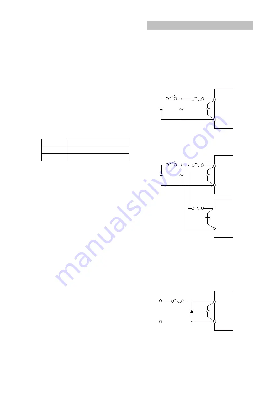
When switches or connectors are used between input
source and PAH300
・
350S24 Series input terminals,
impulse surge voltage is generated due to input throw-
in by switch on/off or due to inserting/ removing of
power module from the active line. For this case,
connect an additional electrolytic capacitor C6 as
shown in fig.1-3 and fig. 1-4.
Recommended Capacitance Value : 220
μ
F and above
(Voltage Rating 50V and above)
Also, in-rush current flows at line throw-in. Therefore,
be sure to verify capability of switch or fuse to
withstand I
2
t at line throw-in.
Fuse
-Vin
+Vin
C1
+
C6
+
Switch
Fig.1-3 Input Filter with Input Switch
Fuse
-Vin
+Vin
C1
+
C6
+
Swtch
Fuse
C1
+
-Vin
+Vin
Fig.1-4 Input Filter when Plural Power Modules
Reverse input connection
Reverse input polarity would cause module damage.
For cases where reverse connections are possible, connect
a protective diode and fuse. Use protective diode with
higher voltage rating than the input voltage, and with
higher surge current rating than the fuse.
Fuse
-Vin
+Vin
C1
+
Fig.1-5 Protection for Reversed Connection of Input


