20
83488001 Revision N
5.2.
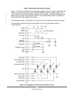
HV ON Push Button (Ref 1)
DO NOT DEPRESS THE HV ON PUSH-BUTTON UNLESS A
SUITABLE CAPACITIVE LOAD IS CONNECTED TO THE POWER
SUPPLY'S OUTPUT CABLE, AND THE LOAD IS CORRECTLY
GROUNDED.
The HV ON push button is a momentary switch that when depressed turns on HV output in
local mode (keyswitch in local position) only if there are no faults present within the supply. If
faults are present when the HV ON button is pushed the supply
will not turn on
, and both
the HV ON and HV OFF LEDs will illuminate. When both the HV ON and HV OFF LEDS are
illuminated together this indicates a Summary Fault. If the keyswitch is in the remote position
the HV ON push button has no function.
5.3.
Status LEDs (Ref 2)
There are 6 status LEDs on the front panel, indicating the state of the HV Output circuit and
various fault detection circuits in the control system.
5.3.1.
HV ON LED
The HV ON LED indicates that the HV output circuit is enabled and the supply will
deliver output current if it is not inhibited by an external inhibit input. If the HV ON and
HV OFF LEDs are illuminated together this indicates a Summary Fault. HV ON LED
is active in local and remote modes.
5.3.2.
HV OFF LED
The HV OFF LED indicates that the HV output circuit is disabled and the supply
cannot deliver output current. If the HV OFF and HV ON LEDs are illuminated
together this indicates a Summary Fault. HV OFF LED is active in local and remote
modes.
5.3.3.
Inhibit LED
If the Inhibit LED is illuminated it indicates the presence of an active inhibit signal, and
the supply will not deliver charging current after the HV ON button is pushed. Inhibit is
applied either via the rear panel mounted BNC connector or either inhibit input via the
remote control connector. Inhibit LED is active in local and remote modes.
5.3.4.
END OF CHARGE LED
The END OF CHARGE or EOC LED indicates that the load or output voltage has
reached the programmed voltage. EOC LED is active in local and remote modes.
5.3.5.
Interlock Open LED
The interlock open LED illuminates if the safety interlock circuit is not closed. The
power supply cannot be turned on if the interlock loop is open. If the interlock loop is
opened when the unit is running (ie when HV in ON), the unit will turn off with a
latching fault, requiring an HV ON/OFF/ON reset cycle before it can be restarted.
Interlock Open LED is active in local and remote modes.
5.3.6.
Load Fault LED
The load fault LED indicates the presence of a fault in the load circuit due to a short
circuit large external capacitor, or an output Overvoltage. An output Overvoltage
condition will cause a latching fault requiring an HV ON/OFF/ON reset cycle before it
can be restarted. Load Fault LED is active in local and remote modes.
Summary of Contents for 802 Series
Page 2: ...PAGE LEFT INTENTIONALLY BLANK ...
Page 10: ...4 83488001 Revision N Notes ...
Page 34: ...28 83488001 Revision N Notes ...
Page 44: ...38 83488001 Revision N Notes ...
Page 57: ......
Page 58: ......
Page 59: ......
Page 60: ......
Page 61: ......
Page 62: ......
Page 63: ......
Page 64: ......
Page 65: ......
Page 66: ......
Page 67: ......
Page 68: ......
Page 69: ......
Page 70: ......
Page 71: ......


