35
83488001 Revision N
To operate more than one unit in parallel all that is required is a parallel control cable, and to
connect the HV output cables together at the load. The output currents from the parallel
supplies simply add together to increase the overall system current. Any model 802 supply,
or any combination of units can be operated in parallel. If at least one model 802L is
connected in a parallel system then the system can be operated without an external
controller by using the 802L as a master supply in local mode.
If status, voltage, and current displays/measurements are required individually for each
supply in a parallel system then the ‘daisy chain’ control cable is not appropriate, and each
unit must be individually connected to a remote control system.
6.4.1.
Parallel system comprising 802L supplies
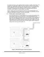
If all of the parallel units are L model supplies then one unit should be operated as the
master supply in either local or remote mode. The other parallel supplies can be
connected to the SLAVE 25-pin D-sub connector on the master unit rear panel (refer to
Figure 14). The SLAVE control cable can be a pin-to-pin ribbon or other cable that is
‘daisy chained’ to the REMOTE connector on each of the SLAVE supplies. Note: The
master 802L supply in a parallel system only displays the status, voltage, and current
output for that unit, not for the entire system. The slave supplies will also display the
voltage and current only for that specific unit.
To Optional Controller
Figure 14 802L Parallel System Control Connections.
Summary of Contents for 802 Series
Page 2: ...PAGE LEFT INTENTIONALLY BLANK ...
Page 10: ...4 83488001 Revision N Notes ...
Page 34: ...28 83488001 Revision N Notes ...
Page 44: ...38 83488001 Revision N Notes ...
Page 57: ......
Page 58: ......
Page 59: ......
Page 60: ......
Page 61: ......
Page 62: ......
Page 63: ......
Page 64: ......
Page 65: ......
Page 66: ......
Page 67: ......
Page 68: ......
Page 69: ......
Page 70: ......
Page 71: ......


