34
83488001 Revision N
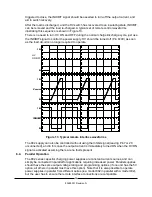
triggered to close, the INHIBIT signal should be asserted to turn-off the output current, and
aid in switch recovery.
After the load is discharged, and the HV switch has recovered to an insulating state, INHIBIT
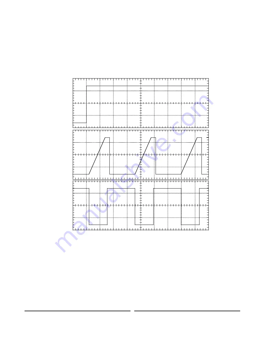
can be removed and the load re-charged. A typical set of remote control waveforms
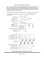
illustrating this sequence is shown in Figure 13.
There is no need to turn HV ON and OFF during the normal charge/discharge cycle, just use
the INHIBIT signal to control the power supply. HV should be turned off (Pin 8=0V) as soon
as the load circuit is no longer required to operate.
Figure 13 Typical remote Interface waveforms
The 802 supply can also be controlled without using the Inhibit signal (leaving Pin 7or 20
unconnected), and in this case the output current is immediately turned ON when the HV ON
signal is activated assuming there are no faults present.
6.4.
Parallel Operation
The 802 series capacitor charging power supplies are constant current sources, and can
simply be connected in parallel for applications requiring increased power. Parallel supplies
should have the same output voltage rating and programming options (if one unit has the 5V
option, all others in parallel must have this option). Note that it is also possible to operate
power supplies in parallel from different series (ie a model 802 in parallel with a model 402),
but the user has to ensure the remote interface connections are compatible.
0V
15V
HV
ON/OFF
0V
10V
V
ANALOG
0V
INHIBIT
15V
0V
15V
0V
10V
V
ANALOG
0V
INHIBIT
15V
Summary of Contents for 802 Series
Page 2: ...PAGE LEFT INTENTIONALLY BLANK ...
Page 10: ...4 83488001 Revision N Notes ...
Page 34: ...28 83488001 Revision N Notes ...
Page 44: ...38 83488001 Revision N Notes ...
Page 57: ......
Page 58: ......
Page 59: ......
Page 60: ......
Page 61: ......
Page 62: ......
Page 63: ......
Page 64: ......
Page 65: ......
Page 66: ......
Page 67: ......
Page 68: ......
Page 69: ......
Page 70: ......
Page 71: ......


