


CM4 App Note 260424 issue 2.1.docx
Document No. 260424
Page 15 of 29
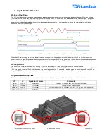
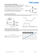
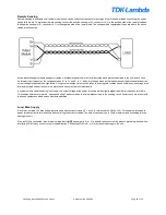
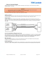
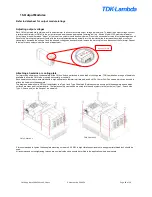
Ripple and Noise
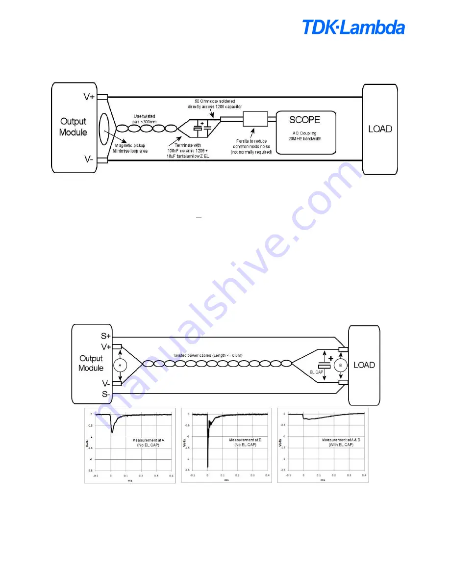
The ripple and noise figures stated in the datasheet are defined based on a standard measuring method. To obtain the same results the same
test setup must be used and care must be taken to eliminate any parasitic noise pickup. The diagram below shows details of the setup and
sources of noise pickup.
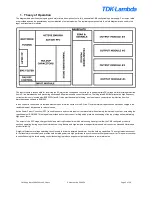
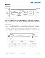
Over Temperature Protection (OTP)
Each output module is protected against excessive temperatures. In the event of an internal temperature exceeding safe levels the output
module will shut off. If the temperature reduces the output module will automatically recover. Should the temperature continue to rise a second
over temperature circuit will shut down the input module and all outputs. To resume operation of the unit, disconnect the AC input voltage for 20
seconds then reconnect. If all temperatures are within specifications the unit will restart. Note that no warning is given on the AC_OK signal for
faults of this type.
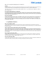
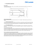
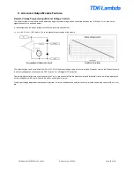
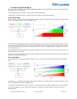
Transient Response
The CM output modules have been especially designed to have high reliability. To achieve this all electrolytic capacitors have been eliminated
from the design. As a result of this, high dynamic load transients can cause relatively high voltage deviations at the output and although the
outputs have a very high loop bandw
idth with typical recovery times of less than 100μs, the voltage deviations may still be excessive for some
applications.
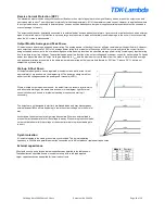
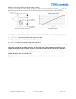
An example application is detailed in the diagram below and shows typical responses at the terminals of the output module and at the load.
Notice that the voltage deviation due to cable inductance exceeds the module response and hence a capacitor located at the module terminals
will have little effect at the load. The optimum solution is to locate a low impedance electrolytic capacitor at the load which will eliminate the
inductive cable drop and reduce the typical voltage deviation at the module.


