CME-5
CME
・
All specifications are subject to change without notice.
• These products are Class
Ι
and must therefore be reliably
earthed and professionally installed in accordance with the
prevailing electrical wiring regulations and the safety standards
covered herein.
• These products are IPX0, and therefore chemicals/solvents,
cleaning agents and other liquids must not be used.
• The first protective earth connection in the final installation must
be marked with the protective earth symbol.
General installation instructions
• These products are designed for continuous operation within an
overall enclosure, and must be mounted such that access to the
mains terminals is restricted. See Clause 16, IEC/EN/UL60601-1.
• These products are NOT suitable for use in the presence of
flammable anaesthetic mixtures with air or with oxygen or with
nitrous oxide.
• These products are classed as ordinary equipment according to IEC/
EN/UL60601-1 and are NOT protected against the ingress of water.
• Connect only apparatus complying with IEC/EN/UL60601-1 to
the signal ports.
• Except for permanently installed equipment as defined in Clause
57.6 of IEC/EN/UL60601-1 the overall equipment in which these
products are installed must have double pole fusing on the input
mains supply. The products themselves have single pole fusing
in the live line.
• These products provide reinforced insulation between mains
and output, with reference to IEC/EN/UL60601-1.
• Reference should be made to local regulations concerning the
disposal of these products at the of their useful life.
• These products have not been assessed to IEC/EN60601-1-2
(EMC) but EMC test data is available from TDK-LAMBDA
Corporation.
Special Instructions for IEC/EN/UL/ 60601-1
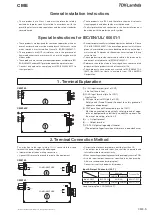
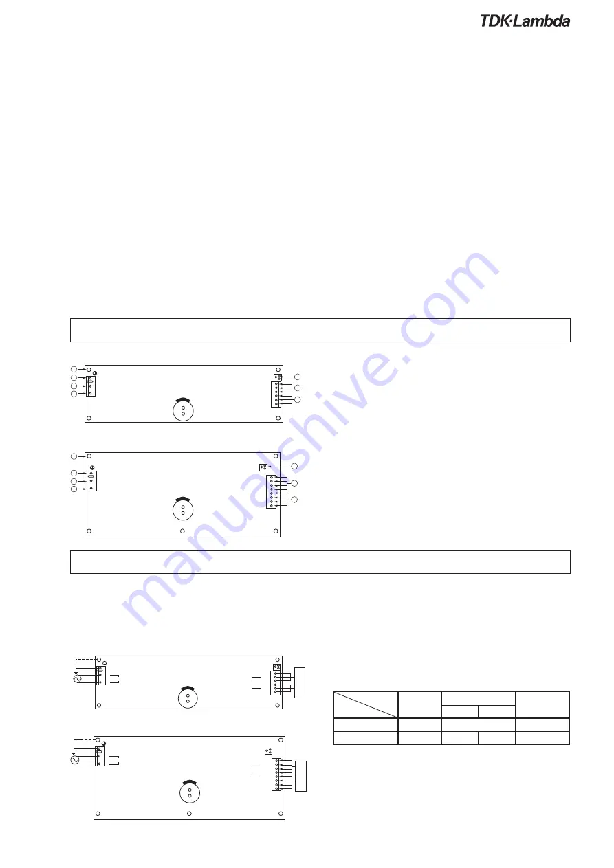
1. Terminal Explanation
CME150
CME240P
(1) L: AC input terminal (pin 1 of CN1)
Live line (fuse in line)
(2) N: AC input terminal (pin 3 of CN1)
Neutral line
(3) FG: Input terminal FG (pin 5 of CN1)
Safety earth (Frame Ground) Connect to safety ground of
apparatus or equipment.
(4) FG: Frame Ground (Connected to pin 5 of CN1)
Must be connected to electrically safety ground of appa-
ratus or equipment by electrically conductive spacers. For
the way of mounting, refer to 4-2
(5) + : + Output terminal
(6)
-
:
-
Output terminal
(7) V.ADJ: Output voltage adjust trimmer.
(The output voltage rises when a trimmer is turnedclockwise.)
2. Terminal Connection Method
Pay attention to the input wiring. If it is connected to wrong
terminal, the power supply will be damaged.
• Input must be off when making connection.
• Connect FG terminal to ground terminal of the equipment.
CME150
CME240
• Output current of each terminal pin must be less than 5A.
• The output load line and input line shall be separated and
twisted to improve noise sensitivity.
• When connecting or removing connector, do not apply stress to PCB.
• Use the input/output connector specified in outline drawing.
Also, use recommended crimping tool.
Connector is not included with this product.
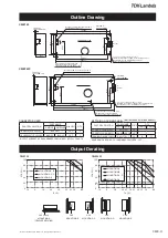
Input & Output Connector (J.S.T)
Connector
Housing
Terminal Pin
CME150
CME240P
Input: CN1
B3P5-VH
VHR-5N
SVH-1T-P1.1
Output: CN51
B6P-VH
VHR-6N
VHR-8N
SVH-1T-P1.1
Hand Crimping Tool : YC-160R(J.S.T)
5
3
1
FG
N
L
CN1
VR51
CN51
1
-
+
2
3
4
5
6
OUTPUT
INTPUT
COMPONENT SIDE
COMPONENT SIDE
-
+
OUTPUT
LOA
D
(%
)
LOA
D
(%
)
85VAC
265VAC1
5
3
1
FG
N
L
CN1
INTPUT
85VAC
265VAC1
CN51
VR51
1
2
3
4
5
6
7
8
5
3
1
FG
N
L
CN1
VR51
CN51
1
2
3
4
5
6
1
2
3
4
5
6
7
CN51
VR51
1
2
3
4
5
6
7
8
5
3
1
FG
N
L
CN1
1
2
3
4
5
6
7


