INSTRUCTION MANUAL
CUS60M Series
TDK-Lambda
<Page>
3
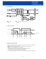
Block Diagram
4
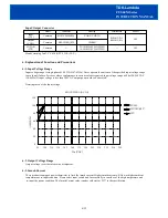
Sequence time chart
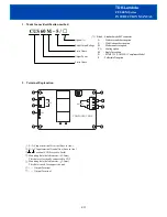
5. Terminal Connection Method
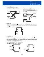
Pay attention to the input wiring. If it is connected to wrong terminal, the power supply will be damaged.
Input must be off when making connections.
terminal must be connected to protective earth of the equipment in Class I installation.
Output current of each terminal pin must be less than 7A.
The output load line and input line shall be separated to improve noise sensitivity.
Do not apply stress to PCB, when connecting or removing connector.
Use input/output connector (housing) specified by the table below.
Use recommended crimping tool. Connector is not included with this product. (Refer to the following)
5/19
Input voltage
Output voltage
0V
Vout
0V
OVP sensing ( 1)
In
pu
t o
n
O
V
P
a
ct
o
n
In
pu
t o
ff
In
pu
t o
n
O
C
P
a
ct
o
n
O
C
P
r
es
et
In
pu
t o
ff
( 1) OVP sensing point
120%~
C
on
tr
ol
C
ir
cu
it
R
ec
ti
fi
er
F
ilt
er
S
w
it
ch
in
g
C
ir
cu
it
OVP
Circuit
Output
Sensing
Inrush Current
Limit Circuit
L
in
e
F
ilt
er
R
ec
tif
ie
r
&
F
ilt
er
Photo-
coupler
OCP
Circuit
L
N
+V
-V
Input
85~265VAC
·
Fuse rating · Circuit topology , switching frequency
2.0A 100KHz
Output

