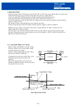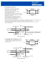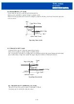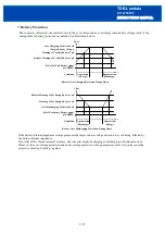
INSTRUCTION MANUAL
EZA2500FC
TDK-Lambda
<Page>
9-2.
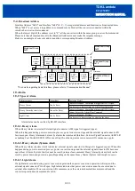
Serial Interface Connector
This converter uses RS-485 as serial interface to the host devices.
The connector type uses the same RJ-45 (shielded) as the general-purpose LAN cables.
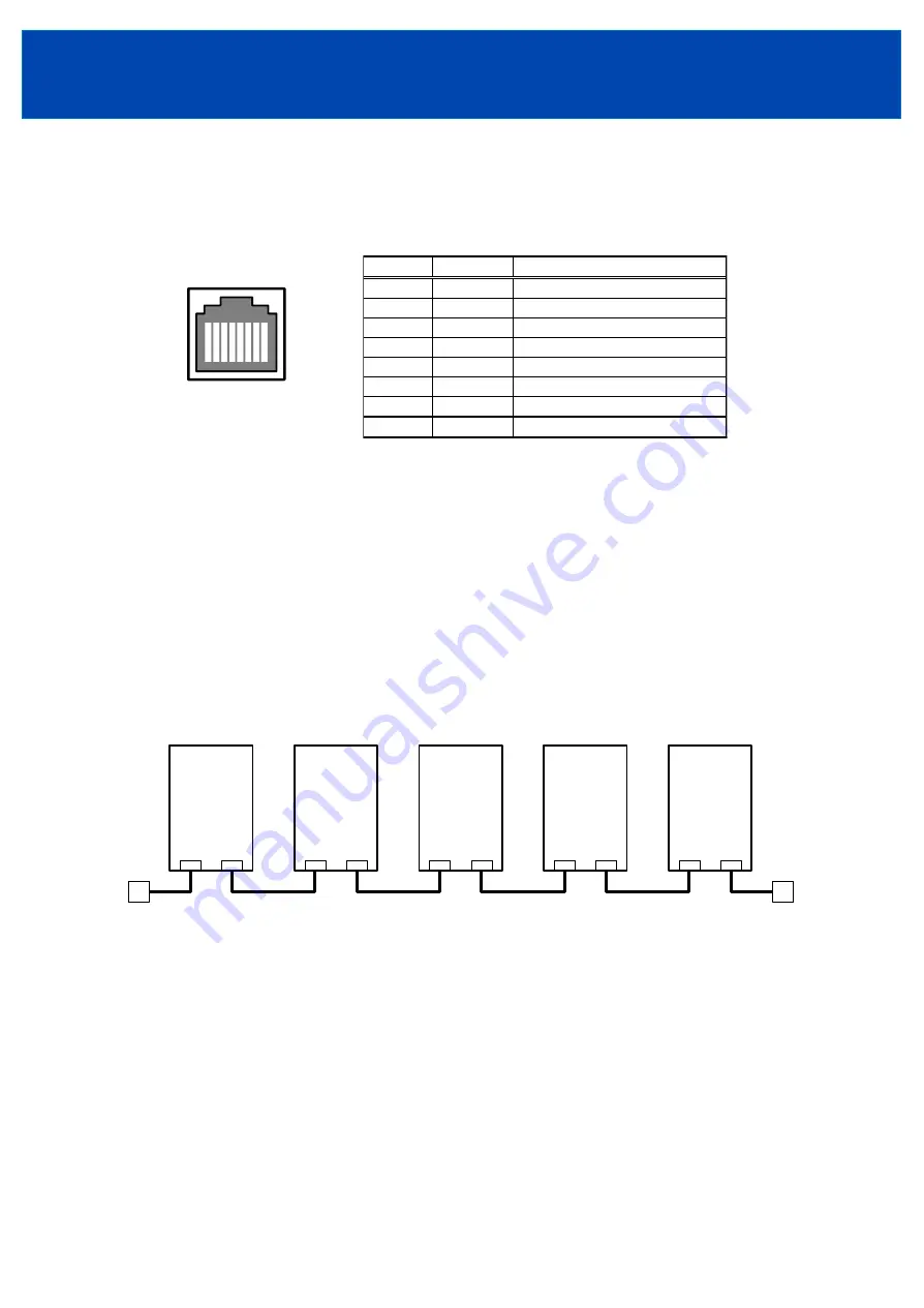
The interface connector layout as seen from the rear panel is shown below.
1
8
2
3
4
5
6
7
It is also possible to use LAN STP cables as connecting cables.
Setting value is stored in the internal memory.
For detail of communication, please refer to "Communication manual".
9-3.
Serial Connection of Multiple Converters
In order to facilitate RS-485 connection, this converter is provided with 2 serial interface connectors.
The interface circuit of this converter functions as intermediate RS-485 connectors.
Due to this feature RS-485 bus can be extended simply by connecting interface cables between converters when
connecting multiple converters to the host devices. (Depending on surrounding environment, there might be a need
to use a termination to connect to one converter or both the converter and the host devices.)
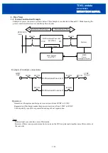
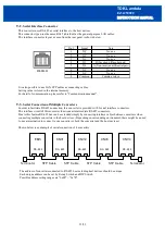
Shown below is an example of serial connection of 4 converters.
STP Cable
STP Cable
STP Cable
STP Cable
Terminator
Terminator
EMS
RS-485
CNV1
RS-485
CNV2
RS-485
CNV3
RS-485
CNV4
RS-485
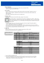
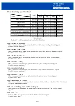
The address of converters connected to RS-485 bus including host devices should be unique.
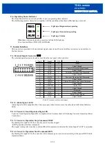
Each unique address can be set by Rotary Switch and DIP Switch.
Possible address setting ranges are "0x00"
~
"0x7E".
13/23
Pin #
Note
1
No use
2
No use
3
No use
4
B (Inverted diffirential pair)
5
A (Non-inverted diffirential pair)
6
No use
7
No use
8
Common return
Signal
NC
Common
NC
NC
D1
D0
NC
NC


