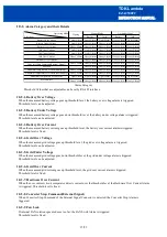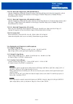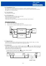
INSTRUCTION MANUAL
EZA2500FC
TDK-Lambda
<Page>
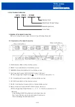
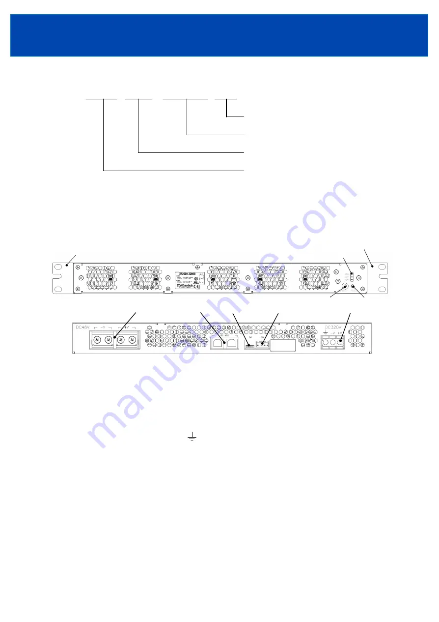
2. Part Number Indication
3. Explain of Terminal Connection
Take care of wiring this power supply. Incorrect wiring will damage this product.
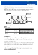
3-1. Explanation of Terminal Connection
①
LED of Indicator (Refer to 8.User Interface section)
②
RESET : Tact Switch (Refer to 8.User Interface section)
③
ADDRESS : Rotary Switch (Refer to 8.User Interface section
)
④
Grid Connection Terminal
(
DC320V HVDC Terminal : M4 Screw
)
DC Power Supply Input Output Terminal , -V, +V
(
The fuse is connected to +V)
⑤
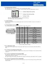
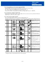
CN : External Signal Connector (Refer to 9.System Interface section)
⑥
SW : DIP Switch (Refer to 8.User Interface section)
⑦
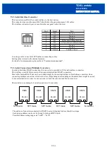
RS-485 : Serial Interface Connector (Refer to 9.System Interface section
)
⑧
Battery Connection Terminal
(
DC48V LVDC Terminal : M5 Screw
)
DC Power Supply Input Output Terminal -V
,
-V, +V, +V
(
The fuse is connected to +V)
4/23
Optional Code
Rated Input / Output Voltage
Rated Output Power
Series Name
EZA 2500 - 32048
①
⑧
⑥
⑦
⑤
④
※
Bracket for Rack Maunt
※
Bracket for Rack Maunt
③
②
※
Warning
When installing EZA2500, load the body on the chassis base side.
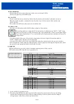
Don
’
t load of the body only by the side brackets for rack mount.
That would damage the bracket and chassis.


