background image

83-530-000 Rev G

30

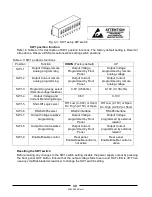
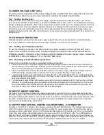
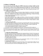
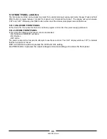
Fig. 4-3: SW1 setup DIP switch

SW1 position function

Refer to Table 4-3 for description of SW1 position functions. The factory default setting is Down for
all positions. Observe ESD precautions when setting switch positions.

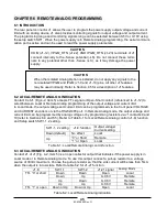
Table 4-3: SW1 positions functions

Position

Function

DOWN

(Factory default)

UP

SW1-1

Output Voltage remote

Analog programming

Output Voltage

Programmed by Front

Panel

Output Voltage

programmed by remote

analog voltage

SW1-2

Output Current remote

analog programming

Output Current

programmed by Front

Panel

Output Current

programmed by remote

analog voltage

SW1-3

Programming range select

(Remote voltage/resistive)

0-5V (0-5Kohm)

0-10V (0-10Kohm)

SW1-4

Output Voltage and

Current Monitoring Range

0-5V

0-10V

SW1-5

Shut-Off Logic select

Off: Low (0-0.6V) or Short
On: High (2-15V) or Open

Off: Low (2-15V) or Open

On: High (0-0.6V) or Short

SW1-6

RS232/485 select

RS232 interface

RS485 interface

SW1-7

Output Voltage resistive

programming

Output Voltage

programmed by Front

Panel

Output Voltage

programmed by external

resistor

SW1-8

Output Current resistive

programming

Output Current

programmed by Front

Panel

Output Current

programmed by external

resistor

SW1-9

Enable/Disable control

Rear panel

Enable/Disable control is

not active

Rear panel

Enable/Disable control is

active

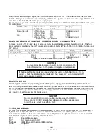
Resetting the SW1 switch

Before making any changes to the SW1 switch setting, disable the power supply output by pressing
the front panel OUT button. Ensure that the output voltage falls to zero and OUT LED is off. Then
use any small flat-bladed screwdriver to change the SW1 switch setting.

Summary of Contents for GENESYS 10KW

Page 1: ...FOR GENESYSTM 10KW 15KW Programmable DC Power Supplies Document 83 530 000 Rev G TDK Lambda Americas Inc High Power Division 405 Essex Road Neptune NJ 07753 Tel 732 922 9300 Fax 732 922 9334 www us T...

Page 2: ......

Page 3: ......

Page 4: ...Americas Inc for warranty service the buyer shall prepay shipping charges to TDK Lambda Americas Inc If the unit is covered under the foregoing warranty then TDK Lambda Americas Inc shall pay the ship...

Page 5: ...use a potential shock hazard that might cause personal injury FUSES Fuses must be changed by authorized TDK Lambda Americas Inc service personnel only For contin ued protection against risk of fire re...

Page 6: ...WARNING sign should not be skipped and all indicated conditions must be fully understood and met The CAUTION sign denotes a hazard An attention to a procedure is called Not follow ing procedure corre...

Page 7: ...31 CHAPTER 5 LOCAL OPERATION 33 5 1 INTRODUCTION 33 5 2 STANDARD OPERATION 33 5 3 OVER VOLTAGE PROTECTION OVP 34 5 4 UNDER VOLTAGE LIMIT UVL 35 5 5 FOLDBACK PROTECTION 35 5 6 OUTPUT ON OFF CONTROL 35...

Page 8: ...GLOBAL OUTPUT COMMANDS 56 7 9 SINGLE BYTE COMMANDS 57 7 10 STATUS ERROR AND SRQ REGISTERS 62 7 11 SERIAL COMMUNICATION TEST SET UP 65 CHAPTER 8 ISOLATED ANALOG PROGRAMMING OPTION 67 8 1 INTRODUCTION 6...

Page 9: ...ating status of the power supply The Front panel controls allow the user to set the output parame ters the protections levels Over Voltage protection Under Voltage limit and Foldback and preview the s...

Page 10: ...ion CV CC 1 2 5 Parallel operation Genesys TM power supplies of the same output voltage and current rating can be paralleled in master slave configuration with automatic current sharing to increase po...

Page 11: ...ngth shielded RJ 45 type plugs eight 8 contacts P N 15 507 201 1 3 1 2 Hardware Strain Relief for AC Cord Output terminal Shield DB25 Programming Plug kit AMP 749809 9 1 3 2 Optional Communication Cab...

Page 12: ...e model numbering system for Genesys TM power supply includes symbols for features and op tions They are separated by dashes The following chart explains the model number for the GEN Power Supply Fami...

Page 13: ...0 2600 1700 1700 100 80 67 50 40 32 20 20 16 13 10 8 7 12 Ripple r m s 5Hz 1MHz c c 15kW mA 100 100 100 50 50 20 20 20 10 10 10 13 Rem sense compensation wire V 1 1 1 1 1 1 5 2 3 3 4 5 5 5 5 5 5 5 5 5...

Page 14: ...t manual adjust by separate encoders OVP UVL manual adjust by Volt Adjust encoder Foldback control CV to CC RS232 485 and IEEE488 2 selection by IEEE or LAN enable switch and DIP switch Re start modes...

Page 15: ...g 40 000 ft 12 000m 2 Output Iout 50A bus bars Iout 37 5 a threaded stud terminal 6 IEMD Option refer to IEMD Option Spec 08 030 100 20C to 70C 10 90 RH Non condensing 4 RS232 RS485 STD Phone Jack con...

Page 16: ...eturn for SO PS_OK J1 3 IF_CO M Isolated Interface Comm on Return for SO PS_OK J1 4 N C J1 5 N C J1 6 N C J1 7 N C J1 8 LOC REM Input for selecting between Local or Remote analog program ming J1 9 VPG...

Page 17: ...selection Local Remote sensing Single or multiple loads Section 3 9 6 Default setting The power supply setting at shipment Section 7 2 4 4 4 1 3 9 4 Table 3 1 Basic setup procedure 3 3 INITIAL INSPEC...

Page 18: ...ply 3 6 AC SOURCE REQUIREMENTS The Genesys TM series can be operated from a nominal 208V 400V or 480V three phase 4 wire 47 63 Hz The input voltage range and current required for each model is specifi...

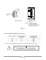
Page 19: ...verse the input cover Figure 3 1 3 7 1 Recommended Cable Size for Input Connection INPUT VOLTAGE CURRENT RMS AMPS PER PHASE RECOMMENDED COPPER WIRE SIZE 208 75 4 AWG 400 45 6 AWG 480 35 7 AWG The AC i...

Page 20: ...rotate the Voltage encoder Ensure that the output voltage varies while the VOLT encoder is rotated The minimum control range is from zero to the maximum rated output for the power supply model Compare...

Page 21: ...inimum and check that the output voltage cannot be de creased below the UVL x 1 05 setting 5 Adjust the UVL limit to the minimum by repeating Sep 1 and rotating the VOLT encoder CCW 3 8 7 Foldback Che...

Page 22: ...dation The output styles vary depending o the output voltage range Platform A B Output Voltage Range 7 5V 80V 100V 300V Vertical Bus Bar Configuration 0 422 in mtg Hole Use 3 8 in dia Bolt Platform C...

Page 23: ...ode should be connected across the output The diode voltage and current rating should be greater than the power supply maximum output voltage and current rating Connect the cathode to the positive out...

Page 24: ...y located output distribution terminals are used the power supply output terminals should be connected to the distribution terminals by pair of twisted and or shielded wires Each load should be separa...

Page 25: ...2 Local sensing The power supply is shipped with the rear panel J2 sense connector wired for local sensing of the out put voltage See Table 3 4 for J2 terminals assignment With local sensing the outpu...

Page 26: ...rear panel sense connector J2 4 Turn On the power supply Notes 1 If the power supply is operating in remote sense and either the positive or negative load wire is not connected an internal protection...

Page 27: ...he TDK Lambda Americas Inc sales or ser vice facility near you for Return Authorization and shipping information Please attach a tag to the power supply describing the problem and specifying the owner...

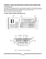
Page 28: ...OLS AND CONNECTORS 4 1 INTRODUCTION The Genesys TM Power Supply series has a full set of controls indicators and connectors that allow the user to easily setup and operate the unit Before starting to...

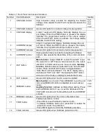
Page 29: ...2 2 7 2 4 7 OUT button Main function Output ON OFF control Press OUT to set the output On or Off Press to reset and turn On the output after OVP or FOLD alarm events have occurred Auxiliary function S...

Page 30: ...nd hold PREV button to toggle between Locked front panel and Unlocked front panel The display will cycle between LFP and UFP Releasing the PREV button while one of the modes is displayed selects that...

Page 31: ...83 530 000 Rev G 28 Fig 4 2 Rear panel connections and controls...

Page 32: ...utput Voltage Current Limit and other con trol functions 4 4 7 J2 Remote sense con nector Connector for making remote sensing connections to the load for regulation of the load voltage and compensatio...

Page 33: ...oltage and Current Monitoring Range 0 5V 0 10V SW1 5 Shut Off Logic select Off Low 0 0 6V or Short On High 2 15V or Open Off Low 2 15V or Open On High 0 0 6V or Short SW1 6 RS232 485 select RS232 inte...

Page 34: ...sion range AWG26 22 Extraction tool AMP 91232 1 or equivalent Manual Pistol grip tool Handle AMP P N 58074 1 Head AMP P N 58063 1 Before making any connection turn the power switch to the Off position...

Page 35: ...e power supply Output Voltage Sec 6 6 J1 12 COM Control Common Return for VMON IMON CV CC LOC REM Connected internally to the negative local sense potential LS J1 13 CV CC Output for Constant Voltage...

Page 36: ...utton and then rotate the VOLTAGE encoder knob The VOLTAGE meter will show the programmed output volt age for 5 seconds after the adjustment has been completed Then the VOLTAGE meter will display OFF...

Page 37: ...power supply output will shut down 5 3 1 Setting the OVP level The OVP can be set when the power supply output is Enabled On or Disabled Off To set the OVP level press the OVP UVL button so that the...

Page 38: ...button to cancel the Foldback protection The power supply output will be disabled and the VOLTAGE display will show OFF Press the OUT button to enable the power supply output 3 Turn the power supply...

Page 39: ...Constant Voltage or Constant Cur rent CV CC signal is an open collector output with a 30V parallel zener at J1 13 referenced to the COM potential at J1 12 connected internally to the negative sense po...

Page 40: ...erature When an OTP shutdown occurs the display show OTP and the ALARM LED blinks Resetting the OTP circuit can be automatic non latched or manual latched depending on the Safe or Automatic restart mo...

Page 41: ...referenced to the negative Sense S potential There fore the circuits used to control each series connected unit must be separated and floated from each other using the Isolated Analog option 2 Using t...

Page 42: ...ply rated output voltage and output current Refer to Fig 5 3 for this operating mode Remote programming in series operation for positive and negative output voltage 1 Programming by external voltage T...

Page 43: ...ld be programmed higher than the output voltage of the master unit to prevent interference with the master unit s control The current limit of each unit should be programmed to the desired load curren...

Page 44: ...application requirements If a fault occurs in one of the units its PS_OK signal will be set to low level and the display will indicate the fault The other units will shut off and their display will i...

Page 45: ...e units default operation a When a unit is programmed to Slave mode it enters the Remote mode with Local Lockout In this mode the front panel controls are disabled to prevent accidental setting change...

Page 46: ...power supplies Programmed Current to zero UVL to zero volts OVP to its maximum value AST OFF OUT OFF Foldback protection OFF Locked Front Panel Fig 5 4 Parallel connection with local sensing MASTER PO...

Page 47: ...1 UNLOCKED FRONT PANEL In this mode the front panel controls are enable to program and monitor the power supply parameters 5 18 2 LOCKED FRONT PANEL In this mode the following front panel controls are...

Page 48: ...elect between Local or Remote Analog programming of the output voltage and current limit In Local mode the output voltage and current limit can be programmed via the front panel VOLTAGE and CURRENT en...

Page 49: ...programming source to the mating plug of J1 as shown in Fig 6 1 Observe correct polarity for the voltage source 7 Set the programming sources to the desired levels and turn the power supply ON Adjust...

Page 50: ...rt between J1 8 and J1 12 refer to Table 4 4 5 Connect the programming resistors to the mating plug of J1 as shown in Fig 6 2 6 Set the programming resistors to the desired resistance and turn the pow...

Page 51: ...Signal name Signal function Signal Return Range SW1 4 VMON Vout monitor J1 11 IMON Iout monitor J1 24 J1 12 0 5V Down VMON Vout monitor J1 11 IMON Iout monitor J1 24 J1 12 0 10V Up Table 6 5 Monitori...

Page 52: ...LOC button The VOLTAGE display will indicate the communication port address 3 Using the VOLTAGE adjust encoder select the address To preview the address at any time press and hold the REM LOC button...

Page 53: ...query is received the power supply will reply and remain in Local mode If a command that affects the output is received the power supply will perform the command and change to Remote mode Serial comm...

Page 54: ...the desired interface RS232 or RS485 using rear panel setup switch SW1 6 Section 4 4 RS232 Down position RS485 Up position 2 Connect rear panel IN connector to the controller RS232 or RS485 port usin...

Page 55: ...units on the bus are connected via their RS485 interface Refer to Figure 7 5 for typical connection Set rear panel setup switch SW1 6 to its UP position Using the Linking cable refer to Fig 7 6 connec...

Page 56: ...he rules of checksum apply also to the acknowledge 7 5 7 Error message If an error is detected in command or query the power supply will respond with an error message Re fer to section 7 6 for details...

Page 57: ...supply 2 CLS Clear status Sets FEVE and SEVE registers to zero refer to Section 7 11 3 RST Reset command Brings the power supply to a safe and known state Output voltage zero Remote non lockout remot...

Page 58: ...Example 200A supply sends 000 50 110 12 200 00 etc 7 7 5 Output control commands cont 7 DVC Display Voltage and Current data Data will be returned as a string of ASCII charac ters A comma will separa...

Page 59: ...g These settings are erased when the supply power is switched Off and the new last settings are saved 25 RCL Recalls last settings Settings are from the last power down or from the last SAV command 26...

Page 60: ...R carriage return character is not included in a single byte command The RST command will not change any setting made by a single byte command All Single Byte commands will be executed in 1 ms or less...

Page 61: ...the Status Event Register SEVE the Fault Condition Register the Fault Enable Register and the Fault Event Register IFEVE All registers will be represented in two Hex bytes Following the register data...

Page 62: ...tive 7 9 5 2 Re enable SRQ with out reading clearing the SEVE Register Send A5 Hex followed by the address of the supply in binary and new SRQ s generated by new events in the Fault Event will be enab...

Page 63: ...on of SRQ is enabled it will remain en abled for the next SRQ X xxxx is the address of the supply in binary Test if MD Mode is Installed Byte 1 1010 1010 Byte 2 xxxx xxxx 0 or 1 Returns a 0 if not ins...

Page 64: ...0 550 500 20 0 475 600 17 60 660 600 17 0 570 7 9 6 Status Control Commands Refer to Section 7 10 for definition of the registers Command Description 1 STT Reads the complete power supply status Retur...

Page 65: ...output is turned On by front panel button or OUT 1 command 4 Over voltage OVP OVP shutdown has occurred The supply output is turned ON by front panel button or OUT 1 command 5 Shut Off SO Rear panel J...

Page 66: ...Enable Register is set to the enable faults SRQs Table 7 12 Fault Enable Register BIT Enable bit name Fault symbol Bit Set condition Bit reset condition 0 LSB Spare bit SPARE 1 AC Fail AC 2 Over Temp...

Page 67: ...s zero Always zero 6 Spare Spare Always zero Always zero 7 MSB Local Mode LCL SENA nn command SENA nn command 4 Status Event Register The Status Event Register will set a bit if a change in the power...

Page 68: ...II Set Up Select Echo characters locally select send line ends with line feed On some PC systems pressing the number keypad Enter will distort displayed messages Use the alphabetic Enter instead 3 Pow...

Page 69: ...SENA xx SENA SEVE 0 AC OTP FLD OVP SO OFF ENA Fault Registers Condition Enable Spare AC Fail Over Temperature Foldback tripped Over Volt Prot Shut Off rear panel Output Off front panel Enable Open 0 1...

Page 70: ...Output current programming temperature coefficient PPM C 100 Input impedance Ohm 1M Absolute maximum voltage Vdc 0 15 Programming Inputs Max voltage between program inputs and supply outputs Vdc 600...

Page 71: ...10V IS510 option Range 4 20mA IS420 option 1 SHLD Shield connected internally to chassis of the supply Chassis ground 2 VPROG_ISO Output voltage programming in put 0 5 0 10V 4 20mA 3 IPROG_ISO Output...

Page 72: ...d 2 to their Up position 4 Set SW1 position 3 to select the programming voltage range Down 0 5V Up 0 10V 5 Set SW1 position 4 to select the monitoring range Down 0 5V Up 0 10V 6 Ensure that SW1 positi...

Page 73: ...d service facilities no parts replacement information is provided in the manual In case of failure unusual or erratic operation of the unit contact a TDK Lambda Americas Inc sales or service facility...

Page 74: ...lay indicates OUP Over Voltage Protection circuit is tripped Turn off the AC power switch Check load connections If analog programming is used check if the OVP is set lower than the output 5 3 No outp...

Reviews: